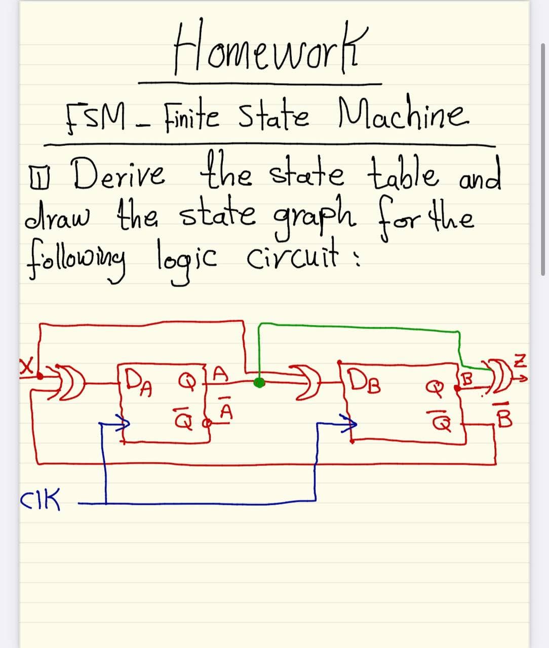
O Derive the state table and draw the state graph for the followoiny logic circuit: DA DB A CIK


Q: Estimate the shape of magnitude response of H(z). Take b=0.5. 2) What is the type of system…
A: NOTE- As per the rules we can answer only 3 sub-parts, please post the remaining sub-parts as the…
Q: 8.51 Using nodal analysis, find I, in the circuit in Fig. P8.51. j1nキ 4/0 A 12/6 V 2/0 A Figure…
A: In this question, We need to determine the current Io using the Norton theorem. We are solving…
Q: 1) Determine if the following system is a linear system. y(n) x(n – 3) + 3x(n) %3D 2) Determine if…
A: For first question we have to check whether system is linear or not. For second question we have…
Q: A 37.5 kVA transformer has a rated core loss and copper losses of 1. 300 W and 500 W. Determine the…
A: 1. Transformer has Rating (R) = 37.5 KVA Core loss (Lcore) = 300w Copper loss (Lcu) = 500w Power…
Q: Q2. The DTFT of x[n] is X(ej@) = Find the following: (1-0.73 e-ja) (a) x[n] (b) DTFT of x'I-n] (c)…
A: As per our guidelines we are supposed to be answer the first three questions only. Kindly repost…
Q: 8.55 Use nodal analysis to find V, in the circuit in Fig. P8.55.
A:
Q: ll 41. For the network of Fig. 15.148: a. Calculate E, IR. and Iz in phasor form. b. Calculate the…
A:
Q: What is the difference between outsourcing and offshoring and why would a company choose to…
A: Outsourcing and offshoring : Outsourcing refers to an business enterprise contracting education…
Q: 4. What parameter of a PPM signal varies in direct proportion to the message signal amplitude? a.…
A: Note: We are authorized to answer the first question since the exact one wasn’t specified. Please…
Q: Find a function to detect an error in the representation of a decimal digit in BCD. In other words,…
A:
Q: Which laws were used by Kirchoff to describe the flow of electrons in a circuit
A: There are two law of Kirchhoff's, Kirchhoff's Voltage Law Kirchhoff's Current Law
Q: use the supe position thearem, bind the current in the 40 A resistor of the circuit shown. sO v 407
A: Given: Circuit diagram
Q: For the circuit shown in Fig.1 (i), find : (i) the output voltage (ii) the voltage drop across…
A: This question belongs to analog electronics . It is based on the concept of zener diode in the…
Q: Electrical Engineering What is the logic function Va Vp o Vg Ve 어 Va 에 오
A: The solution is given below
Q: 1) Estimate the shape of magnitude response of H(z). Take b=0.5. 2) What is the type of system…
A: NOTE- As per the rules we can answer only 3 sub-parts, please post the remaining sub-parts as the…
Q: What happens when the anode-to- cathode voltage exceeds the * ?forward-breakover voltage The device…
A: This is the concept of silicon controlled rectifier.
Q: 5. Find the fundamental period of 1+sin^2 (3t/5)n. a) 10/3 b) 5 с) Зл/5 d) None of the mentioned
A: In this question we will find fundamental time period of given discrete system....
Q: 1. What is the role of AVR at increase or decrease the load? 2. What is the main diffor
A: We are authorized to answer one question at a time, since you have not mentioned which question you…
Q: Q/ Find the total current and current Armatuer and current field ? Ish 50L 50V Dz 122 A2
A:
Q: Q.29: For the ideal transformer circuit shown, find the average power delivered to (1Q) resistor?…
A: An imagined transformer with the following qualities is called an ideal transformer. The resistance…
Q: 2. The variable resistor R in the circuit of Fig. 3.19 is adjusted until it absorbs the maximum…
A:
Q: 59 8.63 Use nodal analysis to find V, in the circuit in Fig. PS.63. 41, V. 10 Figure P8.63
A: In this question, We need to determine the value of the voltage Vo as shown in the circuit using…
Q: What voltage would be needed to provide a
A:
Q: 53. A 37.5 kVA transformer has a rated core loss and copper losses of 300 W and 500 W. Determine the…
A: The solution is given below
Q: Assume the circuit in the picture is part of a third-order low-pass Butterworth filter having a…
A: The circuit diagram is shown below, Here, THe pass band gain(k) is 7.
Q: choose the correct expression for A +A B C D A + B C В + А С O B+AC OC+A B
A: Given: Boolean expression, F=A+A.B.C
Q: Find out the effective resistance of the circuit? R1 = 50 R3=50 R2 = R4 =52 20V 102
A: Given circuit,
Q: The standard unit to measure luminous intensity is called and the symbol is given by
A:
Q: For a RTD temperature sensor, the set point is 100 degrees celsius and the proportional output being…
A: Given, For RTD temperature sensor, Set point, T1=100 °C Proportional output resistance, R01=500 ohms…
Q: H. W2: - Determine the z-transform, including the ROC, pole-zero- plot, for sequence x(n) = (;) u(n)…
A:
Q: aUse nodal analysis to find V, in the circuit in Fig. PR.6l
A:
Q: +12V R1=12K R2 Study the given circuit above. Each diodes has a VF=5V (total voltage across it is…
A:
Q: CO calculate Vth,Rth,Il 1k Ohm 330 Ohm 6 V/1 kHz RL 220 Ohm 330 Ohm
A:
Q: 8.56 Find I, in the circuit in Fig. P8.56 using nodal analysis. 21 -j20 2/0 A 12/6 v 6/0 V Figure…
A: The circuit diagram is shown below,
Q: R1 R3 Vs Vout R2 Vin Figure 2.2 (c) What is the small-signal output voltage, vout, for the circuit…
A: We need to find out output voltage for given circuit.
Q: Q6. Calculate the resonant frequency of the circuit in Fig. Answer. 173.21 rad/s. 50 mH Vm cos wt…
A:
Q: Determine the PIV, turns ratio, the maximum output voltage as well draw the output wave form of the…
A:
Q: A. What values of B correspond to a = 0.970, 0.993, 0.250? (b) What values of a correspond to B= 40,…
A: Although relation between common emitter current gain(β) and common base current gain (α) is given…
Q: An n-type piece of silicon experiences an electric field equal to 0.2 V/um. Calculate the velocity…
A:
Q: 8.58 Use nodal analysis to find V, in the circuit in Fig. PS.58. V. Figure P8.58
A: In this question, We need to determine the voltage Vo using the nodal analysis?
Q: . Two single-phase transformers with equal ratings and turns ratio are operated in parallel to…
A:
Q: Explain the effect of increasing the armature voltage on the behavior of the shunt wound machine…
A: The shunt machine (generator) circuit can be represented as: The EMF equation will be,…
Q: For the figure system 5 sis + 2) 1+ as Find the characteristic equation and bring it to the Evans…
A: Given:
Q: The open-circuit characteristic of a DC generator is also called as characteristics. O internal…
A: There are two types of characteristics of DC generator: No load saturation characteristics Internal…
Q: You are performing a market basket analysis where there are over 5 million different types of…
A: To find the correct answer, we will refer all techniques and then choose relevant option based on…
Q: Discuss High level modulator: circuit diagram and operation - Collector modulator
A:
Q: What is transformer ?
A:
Q: Q5- If x = [3 2 1] and h u(n- 1)-u(n-4) Evaluate y[n] = x[n] * h[n] by the 2 %3D ways.
A: We are supposed to be answer of first question as per guidelines.
Q: 12. Use NAND gates, NOR gates, or combinations of both to implement the following logic expressions…
A: The solution is given below
Q: 5. A 6600/400 volts transformer takes 1.5 A current at a power factor of 0.5 on open circuit.…
A:


Trending now
This is a popular solution!

Step by step
Solved in 3 steps with 3 images


- (a) Differentiate comparatively the analogue and digital representations. (b) If 33210= Xs then find the value of X. (c)1001011.0112 to equivalent decimal (d) What do you know about the logic gates? Explain the AND gate in details. 410 ADiscreet Mathematics Create the logic circuit diagram for F= XY’ + XZF(A,B,C,D) = (B'+D')(A+C'D)+BCD' 1. Find Minterms and Maxter, in short notation 2. Draw logic diagram
- For the sequential logic circuit that detects the 010011 sequence from binary information received from an external input line x and makes the external z output 1 when detected A)create the situation diagram. Describe how it was created B) create the situation chartUse Digital Logic Simulator Fill-in the blank boxes with the correct LOGIC GATE/ Full/Half Adder.Provide a detailed report on the combinational logic circuits below. 1. Magnitude Comparators a. What are magnitude comparators? b. How does it work? c. Applications of magnitude comparators.
- From the following truth table: i) Construct Karnaugh Map (SOP)ii) Design combinational logic circuit using 2-input NAND Gateiii) Design combinational logic circuit using 4:1 MultiplexerSketch a circuit to represent the logic AB’C’D using a. a conventional symbol b. an array logic symbol.1a. A signal that is deasserted is false. True False 1b. The output of a combinational circuit depends only on the input. True False 1c. It is possible to express all logic functions with NAND. True False 1d. The state of the logic block is also called memory. True False
- Binary Subtractors 1. What are binary subtractors? 2. How does it work? 3. Types of binary subtractors. 4. Draw the logic circuit diagram. 5. Show the truth table. (Our subject is logic circuit and switching theory, and our lesson is combination logic circuit)1) Design the logic gates that compare (3) bit binary numbers that are "equal" or "not equal." A0 B0 A1 B1 A2 B2 2) Derive the logic equations for both outputs 3) What type of circuit/system can this be used in an application you could create?Draw the logic diagram for the following functions, then map it using NAND only technology and NOR only technology: F = y’z + y(x + w) Y = A’B’ + B (A + C)+ C’D+ D