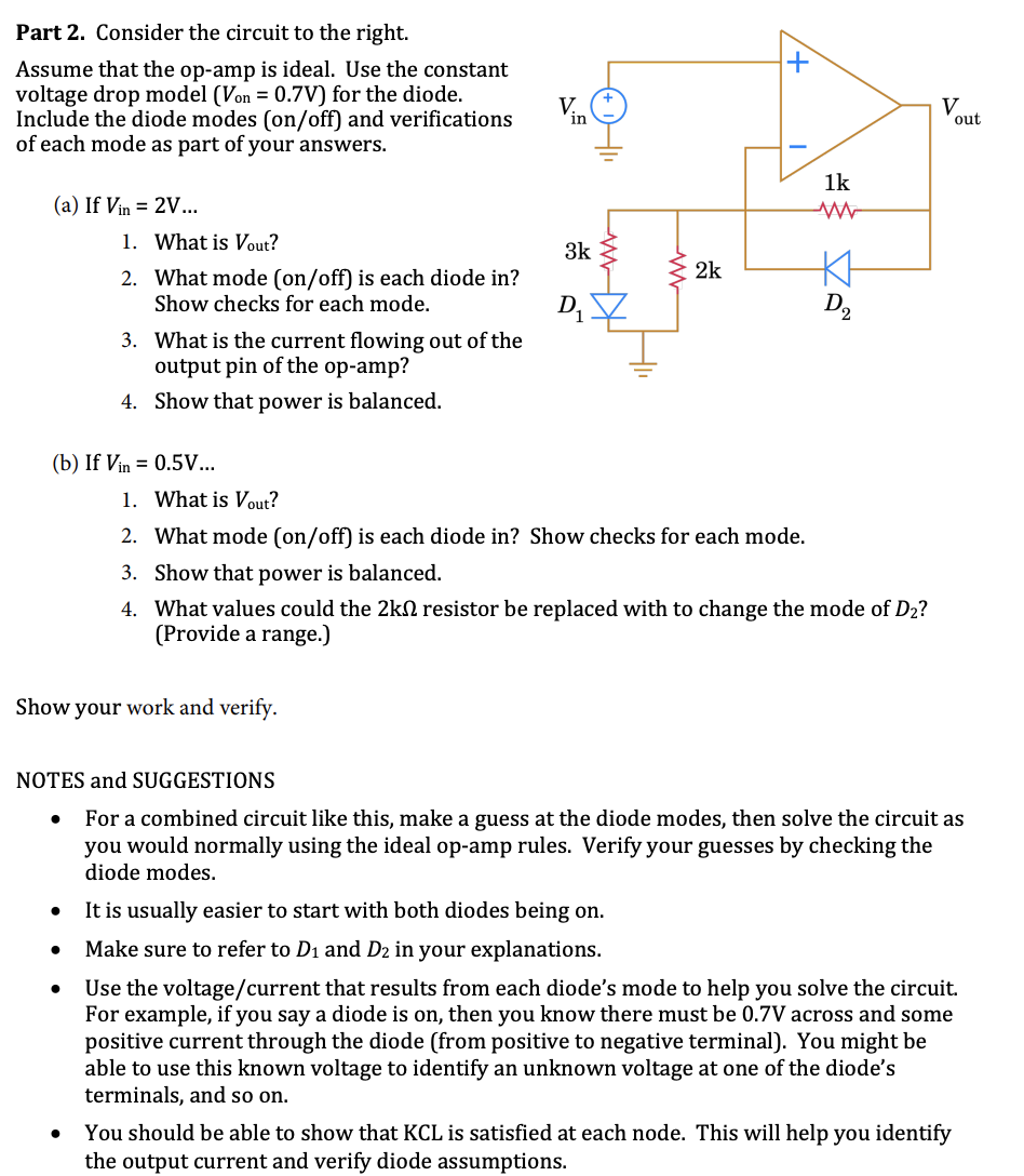
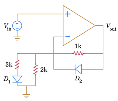
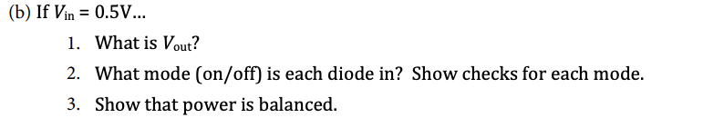
Part 2. Consider the circuit to the right. + Assume that the op-amp is ideal. Use the constant voltage drop model (Von = 0.7V) for the diode. Include the diode modes (on/off) and verifications of each mode as part of your answers. V. in V out 1k (a) If Vin = 2V... 1. What is Vout? 3k 2k 2. What mode (on/off) is each diode in? Show checks for each mode. D2 3. What is the current flowing out of the output pin of the op-amp? 4. Show that power is balanced. (b) If Vin = 0.5V... 1. What is Vout? 2. What mode (on/off) is each diode in? Show checks for each mode. 3. Show that power is balanced. 4. What values could the 2kN resistor be replaced with to change the mode of D2? (Provide a range.)

Introductory Circuit Analysis (13th Edition)
13th Edition
ISBN:9780133923605
Author:Robert L. Boylestad
Publisher:Robert L. Boylestad
Chapter1: Introduction
Section: Chapter Questions
Problem 1P: Visit your local library (at school or home) and describe the extent to which it provides literature...
icon
Related questions
Question

Hello, I am looking for help on part B, please show that KCL is satisfied at nodes, as explained on the bottom, thanks in advance :)

Part 2. Consider the circuit to the right.
Assume that the op-amp is ideal. Use the constant
voltage drop model (Von = 0.7V) for the diode.
Include the diode modes (on/off) and verifications
of each mode as part of your answers.
V
out
in
1k
(a) If Vin = 2V..
1. What is Vout?
3k
2k
2. What mode (on/off) is each diode in?
Show checks for each mode.
D1
D2
3. What is the current flowing out of the
output pin of the op-amp?
4. Show that power is balanced.
(b) If Vin = 0.5V...
1. What is Vout?
2. What mode (on/off) is each diode in? Show checks for each mode.
3. Show that power is balanced.
4. What values could the 2kn resistor be replaced with to change the mode of D2?
(Provide a range.)
Show your work and verify.
NOTES and SUGGESTIONS
For a combined circuit like this, make a guess at the diode modes, then solve the circuit as
you would normally using the ideal op-amp rules. Verify your guesses by checking the
diode modes.
It is usually easier to start with both diodes being on.
Make sure to refer to D1 and D2 in your explanations.
Use the voltage/current that results from each diode's mode to help you solve the circuit.
For example, if you say a diode is on, then you know there must be 0.7V across and some
positive current through the diode (from positive to negative terminal). You might be
able to use this known voltage to identify an unknown voltage at one of the diode's
terminals, and so on.
You should be able to show that KCL is satisfied at each node. This will help you identify
the output current and verify diode assumptions.
Transcribed Image Text:Part 2. Consider the circuit to the right. Assume that the op-amp is ideal. Use the constant voltage drop model (Von = 0.7V) for the diode. Include the diode modes (on/off) and verifications of each mode as part of your answers. V out in 1k (a) If Vin = 2V.. 1. What is Vout? 3k 2k 2. What mode (on/off) is each diode in? Show checks for each mode. D1 D2 3. What is the current flowing out of the output pin of the op-amp? 4. Show that power is balanced. (b) If Vin = 0.5V... 1. What is Vout? 2. What mode (on/off) is each diode in? Show checks for each mode. 3. Show that power is balanced. 4. What values could the 2kn resistor be replaced with to change the mode of D2? (Provide a range.) Show your work and verify. NOTES and SUGGESTIONS For a combined circuit like this, make a guess at the diode modes, then solve the circuit as you would normally using the ideal op-amp rules. Verify your guesses by checking the diode modes. It is usually easier to start with both diodes being on. Make sure to refer to D1 and D2 in your explanations. Use the voltage/current that results from each diode's mode to help you solve the circuit. For example, if you say a diode is on, then you know there must be 0.7V across and some positive current through the diode (from positive to negative terminal). You might be able to use this known voltage to identify an unknown voltage at one of the diode's terminals, and so on. You should be able to show that KCL is satisfied at each node. This will help you identify the output current and verify diode assumptions.
Expert Solution
Step 1

Since you have posted a question with multiple subparts, we will solve the first three sub-parts for you. If you require to 4'th sub-part to be solved, then please re-post the question and mention that subpart.

According to the question, for the circuit shown below

Electrical Engineering homework question answer, step 1, image 1

we need to find

Electrical Engineering homework question answer, step 1, image 2

trending now

Trending now

This is a popular solution!

steps

Step by step

Solved in 3 steps with 4 images

Blurred answer
Knowledge Booster
KVL and KCL
Learn more about
Need a deep-dive on the concept behind this application? Look no further. Learn more about this topic, electrical-engineering and related others by exploring similar questions and additional content below.
Similar questions
  • SEE MORE QUESTIONS
Recommended textbooks for you
Introductory Circuit Analysis (13th Edition)
Electrical Engineering
ISBN:
9780133923605
Author:
Robert L. Boylestad
Publisher:
PEARSON
Delmar's Standard Textbook Of Electricity
Electrical Engineering
ISBN:
9781337900348
Author:
Stephen L. Herman
Publisher:
Cengage Learning
Programmable Logic Controllers
Electrical Engineering
ISBN:
9780073373843
Author:
Frank D. Petruzella
Publisher:
McGraw-Hill Education
Fundamentals of Electric Circuits
Electrical Engineering
ISBN:
9780078028229
Author:
Charles K Alexander, Matthew Sadiku
Publisher:
McGraw-Hill Education
Electric Circuits. (11th Edition)
Electrical Engineering
ISBN:
9780134746968
Author:
James W. Nilsson, Susan Riedel
Publisher:
PEARSON
Engineering Electromagnetics
Electrical Engineering
ISBN:
9780078028151
Author:
Hayt, William H. (william Hart), Jr, BUCK, John A.
Publisher:
Mcgraw-hill Education,