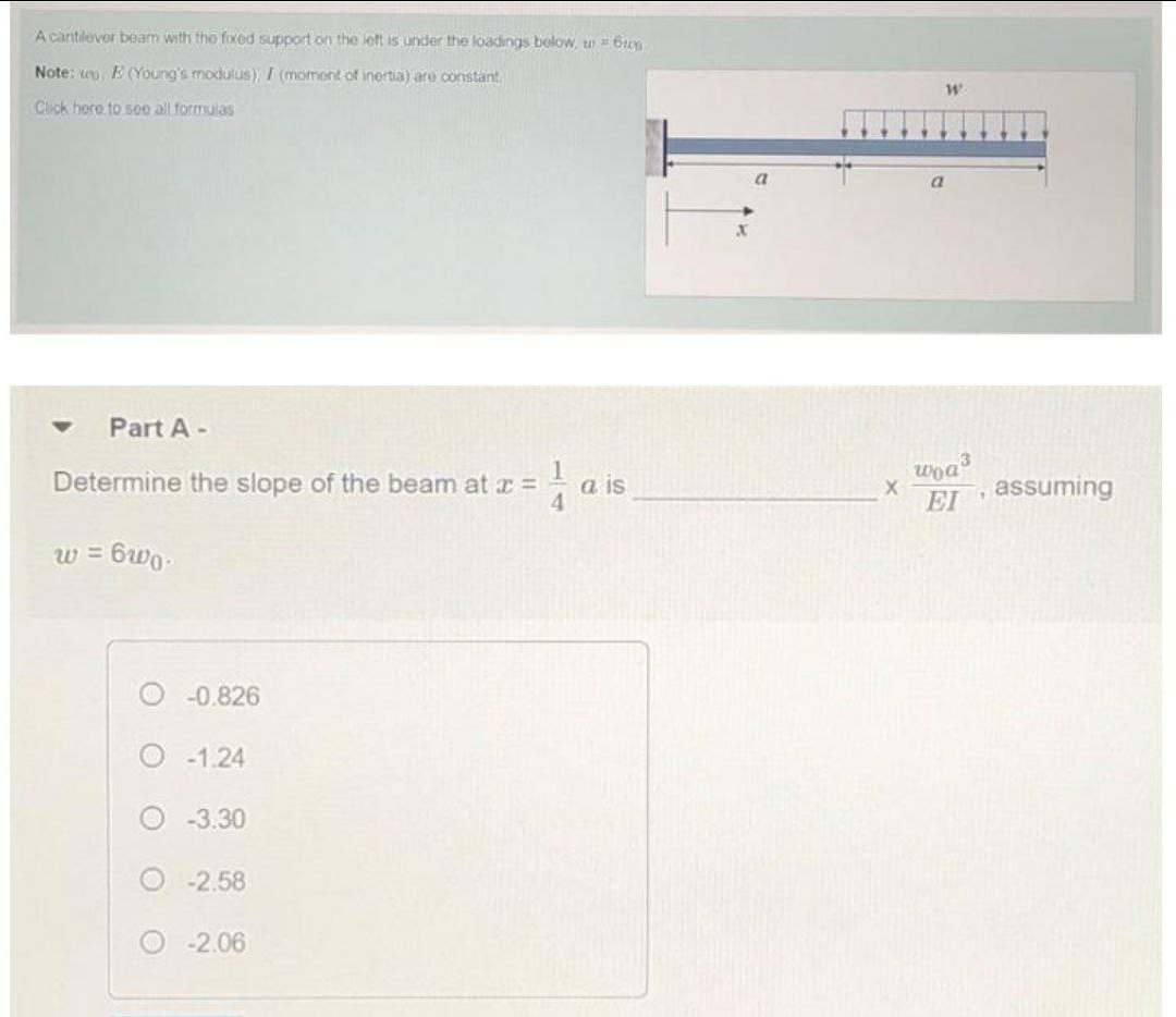
Part A- woa Determine the slope of the beam at c = a is assuming EI w = 6wo-


Q: 12-83. The W250 × 22 cantilevered beam is made of A-36 steel and is subjected to the loading shown.…
A: The free body diagram of the loaded beam is shown below:
Q: Determine the maximum deflection in region AB of the overhang beam. Take E = 29(103) ksi and I = 204…
A: Draw the free-body diagram of the beam.
Q: F12-2. Determine the slope and deflection of end A of the cantilevered beam. E = 200 GPa and I =…
A:
Q: Determine the slope of the shaft at the bearing support A. EI is constant.
A: Find Reactions at A and B by resolving UVL into point loads.
Q: 16-13. Determine the maximum delflection of the beam and the slope at A. El is constant. M. M. в
A:
Q: H.W4 Determine the slope of the simply supported beam at A and deflection at C. E = 200 GPa and I =…
A: Given Load, W = 20 kN Moment, M = 10 kN.m Length, L = 6 m E = 200 GPa Find…
Q: Determine the reactions at A for the cantilever beam subjected to the distributed and concentrated…
A: The magnitude of the uniformly varying load is given by the area of the uniformly varying load…
Q: Determine the slope and the deflection of end B of the cantilever beam. EI is constant.
A:
Q: Determine the reactions on the beam. The loading is varies linearly from 0 kN/m to 10 kN/m and back…
A:
Q: CB 2: Determine the Deflection and Rotation at C by Using Conjugate Beam Method. 9 kN 4 kN 2 E I E I…
A: RAy+RB=13.....(1)Taking moment at A9×1.8-RB×3.6+4×5.4=0RB=37.83.6=10.5 NFrom 1 RAy=2.5 kN
Q: Determine the slope at point A of the beam. EI is constant.
A: Draw the free body diagram of the beam: Use static equilibrium conditions to calculate the…
Q: Use the moment-area theorems and determine the slope at A and deflection at A. El is constant.
A: Given: A cantilever beam having point load at free end,
Q: H.W4 Determine the slope of the simply supported beam at A and deflection at C. E = 200 GPa and I =…
A:
Q: The wooden beam is subjected to the load shown. Determine the deflection and the slope at end B. 6…
A:
Q: For the cantilever beam and loading shown, determine the slope and deflection at the free end
A: To Determine: Slope & Deflection of the cantilever beam We will use the…
Q: 5/97 Determine the reactions at A for the cantilever beam subjected to the distributed and…
A:
Q: Determine the maximum height h from which an 80-lb weight can be dropped onto the end of the A-36…
A: Write the expression for Static deflection due to point load acting at the end.
Q: For the cantilever beam and loading shown, determine the slope and deflection at the free end
A: Calculation of slope at free end (θA)P=PL22EI Where…
Q: F16-6. Determine the slope of the simply supported beam at A. E = 200 GPa and I= 39.9(10 m. 20 kN 10…
A: Given data: The moment of inertia, I = 39.9×10⁻⁶ m4. The modulus of elasticity, E = 200 GPa Due to…
Q: as a I loading that is linearly distributed from w th a fixed support at A. Added support is su = 18…
A: given:wa=470lb/ftwc=260lb/fta=18ftL=23ftP=5000lb
Q: 120KN GOKN/m A D E 240KN.m
A:
Q: Determine the slope of the beam at the pin support A. Consider only bending strain energy. EI is…
A: Assuming the reaction force on A and B is RA and RB then applying force balance on beam, RA+RB=0…
Q: The floor beam of the airplane is subjected to the loading shown. Assuming that the fuselage exerts…
A: Total Forces about vertical is zero ∑FY=0RA+RB=808=640∑BM=0RA12=8086RA=320 lbRB=320 lb Take moment…
Q: For the beam and loading shown,determine (a) the equation of the elastic curve for portion AB of the…
A: Given: The point load is P. The distance between point A and point C is L/2. The distance between…
Q: E 1.0m- W₁ -2.0m- Situation 3: W₁ = 4 kN - m
A: Given that: W1 = distributed force = 4 kN/m It is required to determine the maximum deflection of…
Q: Determine the slope at A and the maximum deflection of the simply supported beam. EI is constant.
A: The reaction force will not develop in the beam as there is no external force is applied. Taking a…
Q: Determine the slope and deflection of end A of the cantilevered beam. E = 200 GPa and I = 65.0(106)…
A: Draw a diagram showing a section x-x at a distance x from the end A of the beam. Here, B denotes…
Q: Determine the slope u at point B of the steel beam as shown. Take E = 200 GPa, I = 60(106) mm4.
A: given cantilever beam ABCpoint load acting on free end P=3kN=3000Nlength of beam…
Q: Determine the slope of the beam at the pin support A. Consider only bending strain energy. EI is…
A: For solving these types of questions use conjugate beam method, as it is very easy to solve these…
Q: Determine the slope at points B and C of the beam shown. Take E = 29(103) ksi and I = 600 in4.
A: The beam is given as,
Q: C -X1 W -L- Α' L- --X²₂- B
A: given; weight density=wCA=LAB=Llets take reaction force at A=RAlets take reaction force at B=RB
Q: Determine the slope and deflection of end A of the cantilevered beam. E = 200 GPa and I = 121(10-6)…
A: Given data as per question E of material = 200 GPa I of material =121× (10-6) m4 Calculations…
Q: Determine the slope and deflection of end A of the cantilevered beam. E = 200 GPa and I = 65.0(106)…
A: Given data M=30 kN·mE=200 GPaI=65×106 mm4
Q: Draw the shear and moment diagram for Beams ACD and DE that are supported at A, C, and E, and are…
A: Shear force diagram represents shear force at every section of the beam. Shear force at any…
Q: 6.28 (a) Determine the equation of the elastic curve for the overhanging beam; and (b) calculate the…
A:
Q: What is the reaction at point A for a simply supported beam shown? Wo 2L O ". L 2 OW.L W L 2W L…
A:
Q: Determine the slope at A and the maximum deflection of the beam. EI is constant.
A: Given: EI is constant To determine: The slope at A The maximum deflection of the beam
Q: The load on a cantilever beam AB has a triangulardistribution with maximum intensity q0 (seefigure).…
A: Given Load = qo Length = L Find Angle of rotation Deflection
Q: Determine the slope and deflection of end A of the cantilevered beam. E = 200 GPa and I = 126(10-6)…
A: Given Data The modulus of elasticity is: E=200 GPa=2×10⁷ kN/m2 The moment of inertia is: I=126×10-6…
Q: For the beam and loading shown, determine (a) the equation of the elastic curve for portion AB of…
A: The free body diagram of the beam is as follows.
Q: Draw the shear and moment diagram for Beams ACD and DE that are supported at A, C, and E, and are…
A: Shear force diagram represents shear force at every section of the beam.. Shear force at any…
Q: 16-46 The W250 x 22 cantilevered beam is made of A-36 steel and is subjected to the loading shown.…
A: givenwidth =22mmthickness of beam =250mmP1=30KNP2=20KNlenngth of beam L=4m=4000mmlet L2=L1=2m=2000mm
Q: Determine the slope at A and the deflection of end C of the overhang beam. Take E = 29(103) ksi and…
A: Draw the free-body diagram of the beam. Apply force equilibrium in a vertical direction.…
Q: 6 kN - 2 m- 1 m B
A: To calculate the deflection and slope at point B, we must first obtain the elastic curve equation…
Q: F12-6. Determine the slope of the simply supported beam at A. E = 200 GPa and I = 39.9(10) m*. 20 kN…
A:
Q: Using IPE shape, design the beam shown. Neglect Vy. F= 13AN, L= Im, o1 = 120MP.. M. B L.
A: For solution refer below images.
Q: Determine the slope at point B. Draw the shear and bending moment diagrams. Assume constant El. W B…
A: Draw the free body diagram of the beam:

Step by step
Solved in 2 steps with 2 images


- A simple beam ACE is constructed with square cross sections and a double taper (see figure). The depth of the beam at the supports is dAand at the midpoint is dc= 2d 4. Each half of the beam has length L. Thus, the depth and moment of inertia / at distance x from the left-hand end are, respectively, in which IAis the moment of inertia at end A of the beam. (These equations are valid for .x between 0 and L, that is, for the left-hand half of the beam.) Obtain equations for the slope and deflection of the left-hand half of the beam due to the uniform load. From the equations in part (a), obtain formulas for the angle of rotation 94at support A and the deflection Scat the midpoint.A simple beam ABC DE supports a uniform load of intensity iy (see figure). The moment of inertia in the central part of the beam (BCD) is twice the moment of inertia in the end parts (AB and DE). Find the deflection Scat the midpoint C of the beam. (Obtain the solution by using the modified form of Castigliano's theorem.)Determine the plastic modulus Z and shape factor/for a W 12 x 14 wide-flange beam. Obtain the cross-sectional dimensions and section modulus of the beam from Table F-l(a) in Appendix F.
- A tapered cantilever beam AB supports a concentrated load P at the free end (see figure). The cross sections of the beam are rectangular tubes with constant width b, outer Tube depth dAat A, and outer tube depth dB— ldA/2 at support B. The tube thickness is constant, as t = dA/20. IAis the moment of inertia of the outer tube at end A of the beam. If the moment of inertia of the tube is approximated as la{x) as defined, find the equation of the deflection curve and the deflection 5^ at the free end of the beam due to the load P.A tapered cantilever beam A B supports a concentrated load P at the free end (see figure). The cross sections of the beam are rectangular with constant width A, depth d Aat support A, and depth ds= ^dJ2 at the support. Thus, the depth d and moment of inertia / at distance x from the free end are, respectively, in which / 4 is the moment of inertia at end A of the beam. Determine the equation of the deflection curve and the deflection S 4at the free end of the beam due to the load P.A symmetric beam A BCD with overhangs at both ends supports a uniform load of intensity q (see figure). Determine the deflection SDat the end of the overhang. (Obtain the solution by using the modified form of Castiglianos theorem.)
- The tapered cantilever beam AB shown in the figure has a solid circular cross section. The diameters at the ends A and B are dAand dB= 2dA, respectively. Thus, the diameter d and moment of inertia / at distance v from the free end are, respectively, in which IAis the moment of inertia at end A of the beam. Determine the equation of the deflection curve and the deflection SAat the free end of the beam due to the load P.The tapered cantilever beam AB shown in the figure has a thin-walled, hollow circular cross sections of constant thickness t. The diameters at the ends A and B are dAand dB= 2dA, respectively. Thus, the diameter d and moment of inertia / at distance x from the free end are, respectively, in which IAis the moment of inertia at end A of the beam. Determine the equation of the deflection curve and the deflection 8 Aat the free end of the beam due to the load P.An overhanging beam ABC is subjected to a couple MAat the free end (see figure). The lengths of the overhang and the main span are a and L, respectively. Determine the angle of rotation 04and deflection S4at end A. (Obtain the solution by using the modified form of Castigliano's theorem.)
- A cantilever beam JA of length Land height/; (see figure) is subjected to a temperature change such that the temperature at the top is 7[ and at the bottom is 7. Determine the equation of the deflection curve of the beam, the angle of rotation BBat end and the deflection 8Bat end B,A fixed-end b earn is subjected to a point load at mid-span. The beam has a rectangular cross section (assume that the h/b ratio is 2) and is made of wood (E = 11GPa). Find height h of the cross section if the maximum displacement of the beam is 2 mm. Calculate the displacement of the beam at the inflection points..20 Determine the plastic moment Mpfor beam having the cross section shown in the figure ey=210 MPa.