as a I loading that is linearly distributed from w th a fixed support at A. Added support is su = 18 ft. Determine the horizontal deflectic
Q: F16-1. Determine the slape and deflection of end A of the cantilevered beam. E = 200 GPa and I =…
A: The moment acting on the cantilever beam is M = 30 kNm. The length of the cantilever beam is L = 3…
Q: For the beam and loading shown, determine the deflection at point C. Use E= 200 GPa
A: Given data Applied concentric moment Mo= 60kNm Length of the beam L = 4.8m Youngus modulus of the…
Q: H.W1 The beam is subjected to the linearly varying istributed load. Determine the maximum deflection…
A: Given Length = L Load, P = w0 Find Deflection
Q: Q.1 The beam below is loaded unsymmetrically. Determine the slope at A (OA)and deflection (A) at the…
A:
Q: F12-2. Determine the slope and deflection of end A of the cantilevered beam. E = 200 GPa and I =…
A:
Q: At what distance a should the journal bearing supports at A and B be placed so that the deflection…
A:
Q: Using Castigliano s theorem for the beam and loading shown determine: a) the vertical deflection at…
A: The theorem in which the strain energy of loaded beam with differentiated with respect to applied…
Q: Determine the position a of the roller support B in terms of L so that the deflection at end C is…
A: Draw the free-body diagram of the beam.
Q: Determine the internal moments at each joint using Slope-deflection equation method. El is constant.…
A:
Q: Determine the magnitude of the vertical deflection of
A: Given data; Flexural rigidity,EI=200 N.m2Applied moment,Ma=1 mLength,l=2 mDetermine the magnitude of…
Q: Use Castigliano's Theorem to determine the reaction force at B and the deflection at A in terms of…
A: Consider an imaginary load W at a distance x from the free end A. The moment at a distance x :…
Q: Determine the slope and the deflection of end B of the cantilever beam. EI is constant.
A:
Q: The two bars are pin connected at D. Determine the slope at A and the deflection at D. EI is…
A:
Q: P = 150 kN PROBLEM 9.13 For the beam and loading shown, determine the deflection at point C. Use E =…
A: Data given-
Q: Determine the slope at C and deflection at B. EI is constant.
A: Given Data: The cantilever beam is subjected to uniformly distributed load w at the second half of…
Q: From the given figure shown, determine the deflection at the mid-span [in terms of /EI). Assume…
A: For solution refer below images.
Q: Determine the equations of the elastic curve using the coordinates x1 and x3. What is the slope and…
A: Taking moment about a cross section passing through x1 and applying pure bending equation, Here, E…
Q: A B C P. F ЗЕ For the deflection at C to be zero, the ratio PIF is
A:
Q: Use the moment-area theorems and determine the slope at A and deflection at A. El is constant.
A: Given: A cantilever beam having point load at free end,
Q: Question 2 A beam ABCD, 6 m long, is simply-supported at the right-hand end D and at a point B 1 m…
A:
Q: Determine the equations of the elastic curve using the x1 and x2 coordinates, and specify the slope…
A:
Q: For the cantilever beam and loading shown, determine the slope and deflection at the free end
A: To Determine: Slope & Deflection of the cantilever beam We will use the…
Q: Determine the slope at C and the deflection at B. EI is constant.
A: Given : The length of the beam is L = 2a The moment acting in the beam is M0 = Pa The load acting…
Q: 6 kN Use the moment-area theorems and determine the slope at A and deflection at A. EI is constant.…
A:
Q: 19 ¡IF 4m 3m 2m 2m The rigid beam is supported by a pin at A and wires BD and CE. If the load P on…
A: The deflection under the load P is 7.14 mm downwards. Therefore, the option (b) is correct answer.
Q: For the beam and loading shown, determine the deflection at point C. Use E=29 *106 psi..
A: Write the expression for deflection at point C.
Q: determine the deflection of the plate.
A: Given P=55 kip G=150 ksi To determine: The deflection of the plate
Q: = 150 kN PROBLEM 9.13 For the beam and loading shown, determine the deflection at point C. Use E =…
A:
Q: Determine the magnitude of the maximum deflection using double integration method. Use E = 200 x10^6…
A:
Q: Determine the slope and deflection of end A of the cantilevered beam. E =250 GPa and I = 70.0 (106)…
A:
Q: A simply-supported beam, 9 m in length, is subjected to a uniform load of 20 kN/m applied at the…
A:
Q: By using moment-area method, determine the slope at B and deflection at C. El is constant. 10 kN A C…
A:
Q: The W14 * 43 simply supported beam is made of A-36 steel and is subjected to the loading shown.…
A: V = -Wx/384EI (16x3 - 24Lx2 + 9L3) ΔC1 = [V]x=L/2 = -5WL4 / 768 EI V = -5*2*204 / 768 EI V = -…
Q: C -X1 W -L- Α' L- --X²₂- B
A: given; weight density=wCA=LAB=Llets take reaction force at A=RAlets take reaction force at B=RB
Q: BP1: A cantilevered beam of constant El and length L is supporting a concentrated load F at x=L.…
A:
Q: *16–56. Determine the deflection at end E of beam CDE. The beams are made of wood having a modulus…
A:
Q: 18 kN 18 kN/m For the beam and loading shown, determine the deflection at |B C W250 × 22.3 point B.…
A: Answer: The deflection at point B is 5.12 mm.
Q: The W14 * 43 simply supported beam is made of A992 steel and is subjected to the loading shown.…
A: To find-: The deflection at its center C. Given-: The dimension of the beam is d=14×43. The material…
Q: 10 kN 3 kN/m A 3 m
A:
Q: Use the conjugate-beam method and determine the slope just to the left and just to the right of the…
A: Given data as per question M=20KNmL=7mEI=10000 KNm2drawing FBD of the system considering…
Q: 12-22. Determine the elastic curve for the cantilevered W14 X 30 beam using the x coordinate.…
A:
Q: 11B. Using the slope deflection method, determine the end moments of the given frame. 75KN EI = 2.00…
A:
Q: The beam has is supported and loaded as shown. EI is constant. Determine: a) The elastic…
A: The given problem will be solved by using integration method. The moment taken at a section will be…
Q: 30 kN-m Determine the slope and deflection at A. El = 200 GPa and / = 60.0x10°mm.
A:
Q: *12-40. Determine the slope at A and the deflection of end Cof the overhang beam. Take E=29(103) ksi…
A:
Q: Determine the moment M0 in terms of the load P and dimension a so that the deflection at the center…
A: Sketch the deflection of the beam due to load and moments on both sides of the beam by using super…
help me asap plss :((
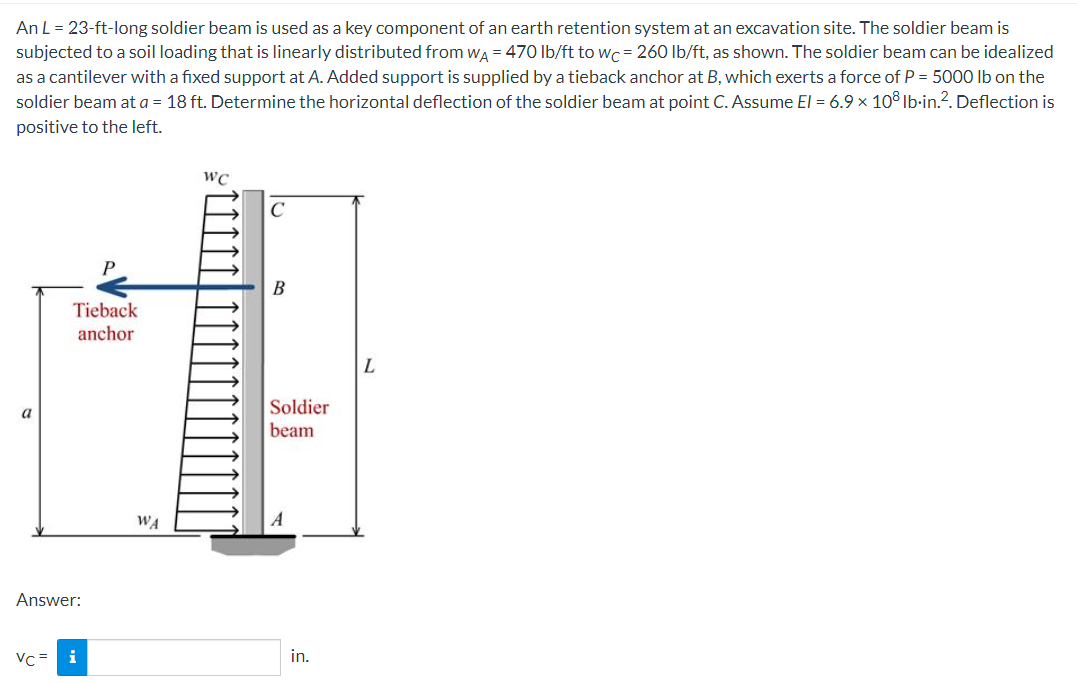
Step by step
Solved in 2 steps with 1 images
- A sandwich beam having steel faces enclosing a plastic core is subjected to a bending moment M = 5 kN · m. The thickness of each steel face is 1 = 3 mm with modulus of elasticity E = 200 GPa, The height of the plastic core is hp= 140 mm, and its modulus of elasticity is Ep= 800 MPa. The overall dimensions of the beam are h = 146 mm and h = 175 mm. Using the transformed-section method, determine the maximum tensile and compressive stresses in the faces and the core.Beam AB has an elastic support kR at A, pin support at B, length L, height h (see figure), and is heated in such a manner that the temperature difference T2T1 between the bottom and top of the beam is proportional to the distance from support A. Assume the temperature difference varies linearly along the beam: T2T1=T0x in which T0 is a constant having units of temperature (degrees) per unit distance. Assume the spring at A is unaffected by the temperature change. Determine the maximum deflection max of the beam, Repeat for a quadratic temperature variation along the beam, so T2T1=T0x2 What is max for parts (a) and (b) if kR goes to infinity?A square wood platform is 8 ft × 8 ft in area and rests on masonry walls (see figure). The deck of the platform is constructed of 2-in. nominal thickness tongue-and-groove planks (actual thickness 1.5 in.; sec Appendix CL) supported on two S-ft long beams. The beams have 4 in. × (i in. nominal dimensions (actual dimensions 3.5 in. × 5.5 in.). The planks arc designed to support a uniformly distributed load n ( lb/ft" i acting over the entire top surface of the platform. I be allowable bending stress for the planks is 2400 psi and the allowable shear stress is 100 psi. W ben analyzing the planks, disregard their weights and assume that their reactions are uniformly distributed over the top surfaces of the supporting beams. (a) Determine the allowable platform load Mr. (lb/ft2) based upon the bending stress in the planks. (b) Determine the allowable platform load if-. (lb/ft-) based upon the shear stress in the planks. (c) Which of the preceding values becomes the allowable load alolow on the platform? Hints: Use care in constructing the loading diagram for the planks, noting especially that the reactions are distributed loads instead of concentrated loads. Also, note that the maximum shear forces occur at the inside faces of the supporting beams.
- An S6 × 12.5 steel cantilever beam AB is supported by a steel tic rod at B as shown. The tie rod is just taut when a roller support is added at Cat a distance s to the left of £, then the distributed load q is applied to beam segment AC, Assume E = 30 × 106 psi and neglect the self-weight of the beam and tie rod. Sec Table F-2(a) in Appendix F for the properties of the S-shape beam. (a) What value of uniform load q will, if exceeded, result in buckling of the tie rod if L1, =6 ft, s = 2 ft, H = 3 ft, and d = 0.25 in.? (b) What minimum beam moment of inertia ibis required to prevent buckling of the tie rod if q = 200 lb/ft, L1, = 6 ft, H = 3 ft, d = 0.25 in., and s = 2 ft? (c) For what distance s will the tic rod be just on the verge of buckling if q = 200 lb/ft, L1= 6 ft, M = 3 ft, and d = 0.25 in.?Beam ACB hangs from two springs, as shown in the figure. The springs have stiffnesses Jt(and k2^ and the beam has flexural rigidity EI. What is the downward displacement of point C, which is at the midpoint of the beam, when the moment MQis applied? Data for the structure are M0 = 7.5 kip-ft, L = 6 ft, EI = 520 kip-ft2, kx= 17 kip/ft, and As = 11 kip/ft. Repeat part (a), but remove Af0 and instead apply uniform load q over the entire beam.A cantilever beam of a length L = 2.5 ft has a rectangular cross section {b = 4in,, h = Sin,) and modulus E = 10,000 ksi. The beam is subjected to a linearly varying distributed load with a peak intensity qQ= 900 lb/ft. Use the method of superposition and Cases 1 and 9 in Table H-l to calculate the deflection and rotation at B.
- Beam ABC is loaded by a uniform load q and point load P at joint C. Using the method of superposition, calculate the deflection at joint C. Assume that L = 4 m, a =2ra, q = 15 kN/m, P = 7.5 kN, £ = 200 GPa, and / = 70.8 X 106 mm4.A simple beam with an overhang is subjected to d point load P = 6kN. If the maximum allowable deflect ion at point C is 0.5 mm, select the lightest W360 section from Table F-l{b) that can be used for the beam. Assume that L = 3 m and ignore the distributed weight of the beam.A heavy object of weight W is dropped onto the midpoint of a simple beam AB from a height h (see figure). Obtain a formula for the maximum bending stress ^ma* due to tne filing weight in terms of h, st, and 5st, where it is the maximum bending stress and Sstis the deflection at the midpoint when the weight W acts on the beam as a statically applied load. Plot a graph of the ratio o"max/ö"it (that is, the ratio of the dynamic stress to the static stress) versus the ratio iifS^r(Let h/S^ vary from 0 to 10.)
- A r o lukI f/frm f «m t ub e of ou t sid e d ia met er ^ and a copper core of diameter dxare bonded to form a composite beam, as shown in the figure, (a) Derive formulas for the allowable bending moment M that can be carried by the beam based upon an allowable stress <7Ti in the titanium and an allowable stress (u in the copper (Assume that the moduli of elasticity for the titanium and copper are Er- and £Cu, respectively.) (b) If d1= 40 mm, d{= 36 mm, ETl= 120 GPa, ECu= 110 GPa, o-Ti = 840 MPa, and ctqj = 700 MPa, what is the maximum bending moment Ml (c) What new value of copper diameter dtwill result in a balanced design? (i.e., a balanced design is that in which titanium and copper reach allow- able stress values at the same time).A propped cantilever beam, fixed at the left-hand end A and simply supported at the right-hand end B, is subjected to a temperature differentia] with temperature T1on its upper surface and T2on its lower surface (see figure).A two-axle carriage that is part of an over head traveling crane in a testing laboratory moves slowly across a simple beam AB (sec figure). The load transmitted to the beam from the front axle is 2200 lb and from the rear axle is 3800 lb. The weight of the beam itself may be disregarded. Determine the minimum required section modulus S for the beam if the allowable bending stress is 17,0 ksi, the length of the beam is 18 ft, and the wheelbase of the carriage is 5 ft. Select the most economical I-beam (S shape) from Table F-2(a), Appendix F.