per is provided at the en- 1. Apply the appropriate welding symbol(s) to each of the orthographic views to indicate the welds shown in the pictorial representations (a) through (d). a. b. SIGNIFICANCE TOP VIEW SIGNIFICANCE FRONT VIEW с. d. SIGNIFICANCE FRONT VIEW SIGNIFICANCE FRONT VIEW 2. When is the size of fillet welds not included in the welding symbol? 3. Sketch a symbol that indicates the following weld. 6. LFILLET WELD- ALL-AROUND 7. Copyright © Cengage Learning Copyright © Cengage Learning Copyright © 2015 Cengage Learning
per is provided at the en- 1. Apply the appropriate welding symbol(s) to each of the orthographic views to indicate the welds shown in the pictorial representations (a) through (d). a. b. SIGNIFICANCE TOP VIEW SIGNIFICANCE FRONT VIEW с. d. SIGNIFICANCE FRONT VIEW SIGNIFICANCE FRONT VIEW 2. When is the size of fillet welds not included in the welding symbol? 3. Sketch a symbol that indicates the following weld. 6. LFILLET WELD- ALL-AROUND 7. Copyright © Cengage Learning Copyright © Cengage Learning Copyright © 2015 Cengage Learning

Welding: Principles and Applications (MindTap Course List)
8th Edition
ISBN:9781305494695
Author:Larry Jeffus
Publisher:Larry Jeffus
Chapter4: Shielded Metal Arc Welding Of Plate
Section: Chapter Questions
Problem 25R: Can a tee weld be strong if the welds on both sides do not have deep penetration? Why or why not?

Related questions
Question
Transcribed Image Text:Copyright Cengage Learning
Copyright © Cengage Learning Copyright ©2015 Cengage Learning
b.
Copyright © Cengage
Leaming
Copyright © Cengage Learning
T
Copyright 2015 Cengage Learning
Weldment Fabrications w 143
UNIT 12 Fillet Welds 157
LINN
UNIT 12: REVIEW A
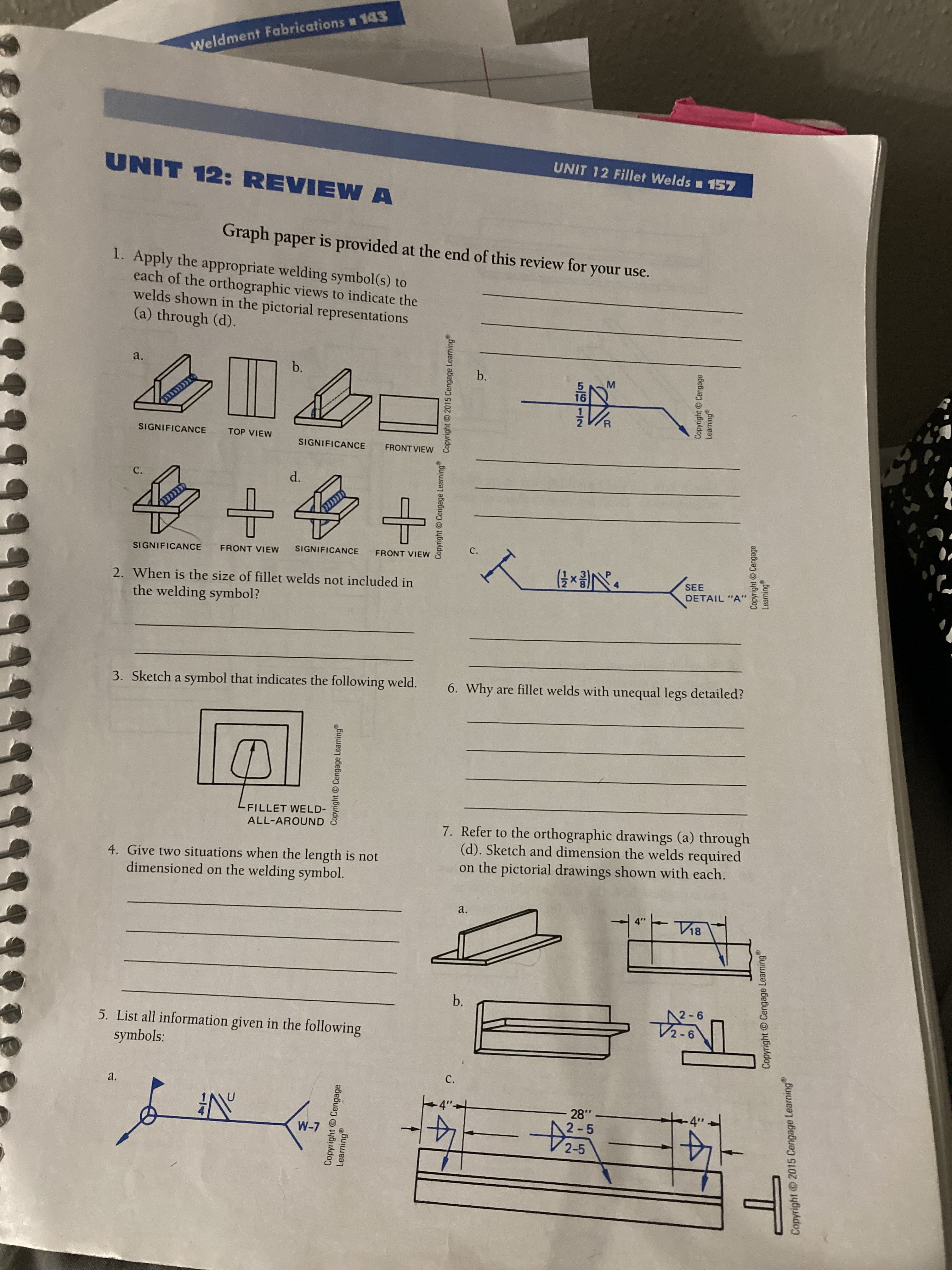
Graph paper is provided at the end of this review for your use.
1. Apply the appropriate welding symbol(s) to
each of the orthographic views to indicate the
welds shown in the pictorial representations
(a) through (d).
a.
b.
b.
M.
16
SIGNIFICANCE
TOP VIEW
SIGNIFICANCE
FRONT VIEW
C.
d.
SIGNIFICANCE
FRONT VIEW
SIGNIFICANCE
FRONT VIEW
2. When is the size of fillet welds not included in
SEE
DETAIL "A"
the welding symbol?
3. Sketch a symbol that indicates the following weld.
6. Why are fillet welds with unequal legs detailed?
-FILLET WELD-
7. Refer to the orthographic drawings (a) through
(d). Sketch and dimension the welds required
on the pictorial drawings shown with each.
ALL-AROUND
4. Give two situations when the length is not
dimensioned on the welding symbol.
a.
12-6
2-6
5. List all information given in the following
symbols:
C.
a.
.87
2-5
14
Transcribed Image Text:Copyright © Cengage Learning
Copyright © Cengage Learning
Copyright 2015 Cengage Learning
oher Side
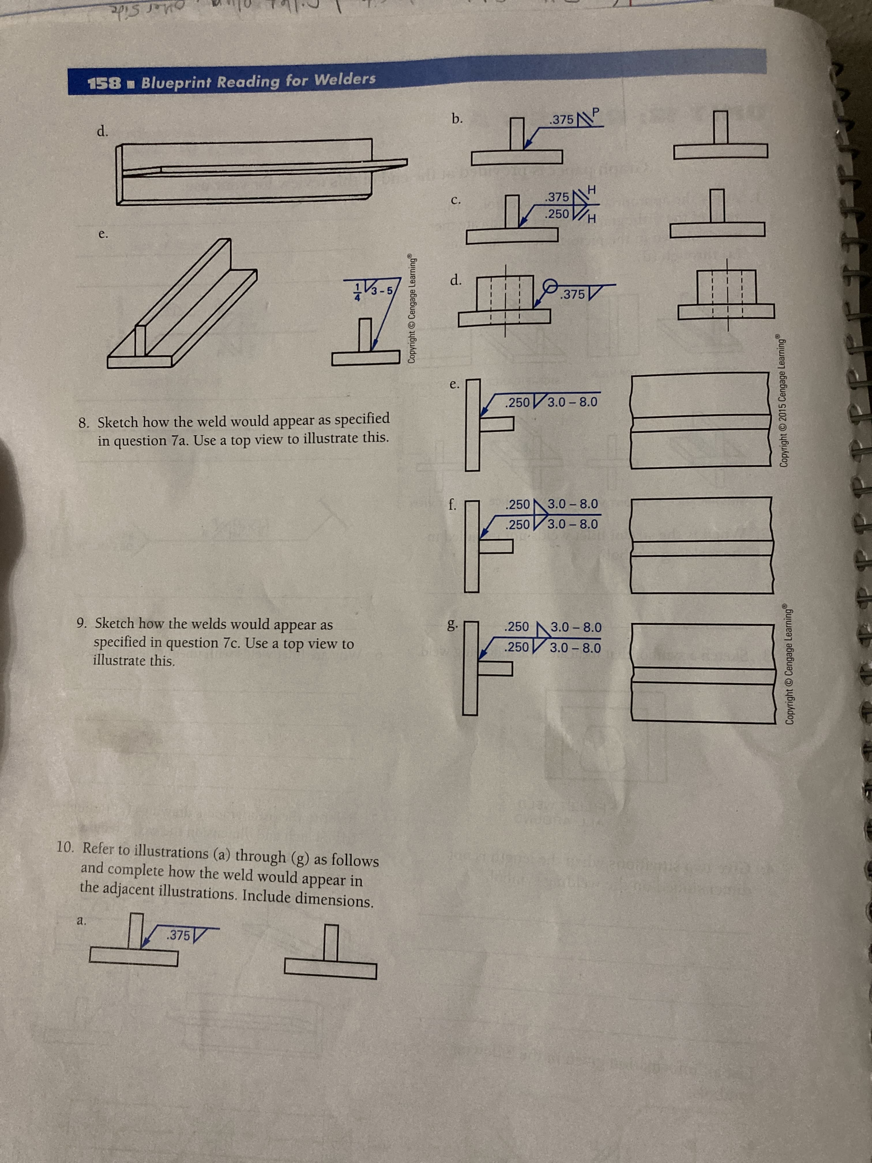
158 Blueprint Reading for Welders
b.
.375N
.375
C.
.250
- 5
d.
.375
e.
.250 3.0-8.0
8. Sketch how the weld would appear as specified
in question 7a. Use a top view to illustrate this.
.250
3.0 - 8.0
.250
3.0- 8.0
9. Sketch how the welds would appear as
specified in question 7c. Use a top view to
illustrate this.
g.
.250
3.0 - 8.0
.250
3.0 - 8.0
10. Refer to illustrations (a) through (g) as follows
and complete how the weld would appear in
the adjacent illustrations. Include dimensions.
a.
Expert Solution
This question has been solved!
Explore an expertly crafted, step-by-step solution for a thorough understanding of key concepts.

This is a popular solution!

Trending now
This is a popular solution!

Step by step
Solved in 4 steps with 3 images

Recommended textbooks for you
Welding: Principles and Applications (MindTap Cou…
Mechanical Engineering
ISBN:
9781305494695
Author:
Larry Jeffus
Publisher:
Cengage Learning
Welding: Principles and Applications (MindTap Cou…
Mechanical Engineering
ISBN:
9781305494695
Author:
Larry Jeffus
Publisher:
Cengage Learning