Problem 1: Fig. 1 shows a proposed method to eliminate the undesirable effects of a measurable load force in a robotic application. You are asked to compare the controlled system design (with and without force feedforward controller G(s). In Fig. 1, Gp, GL are known. The rate-sensor gain k, and the controllers (G. and Gr) are to be designed. F(s) G(s) Switch GL(s) R(s) G(s) G,(s) C(s) The plant transfer function is given by ks 20 G,(s) = Fig. 1 s(s+1)(s+4) 1) Consider F(s) = 0 and G(s) = 1: a) Redraw the block-diagram into the following form, and determine the open-loop and closed-loop transfer functions of the unity-feedback system in terms of the rate-sensor gain k. E(s) R(s) G(s) → C(s) b) Determine the value of k such that the closed-loop complex poles is -1 ± j2.4. Find the corresponding damping ratio and natural frequency, and third pole. c) Use the value of k determined in (1b), determine the steady-state error of the closed loop system when R(s) is a unit ramp-input.
Problem 1: Fig. 1 shows a proposed method to eliminate the undesirable effects of a measurable load force in a robotic application. You are asked to compare the controlled system design (with and without force feedforward controller G(s). In Fig. 1, Gp, GL are known. The rate-sensor gain k, and the controllers (G. and Gr) are to be designed. F(s) G(s) Switch GL(s) R(s) G(s) G,(s) C(s) The plant transfer function is given by ks 20 G,(s) = Fig. 1 s(s+1)(s+4) 1) Consider F(s) = 0 and G(s) = 1: a) Redraw the block-diagram into the following form, and determine the open-loop and closed-loop transfer functions of the unity-feedback system in terms of the rate-sensor gain k. E(s) R(s) G(s) → C(s) b) Determine the value of k such that the closed-loop complex poles is -1 ± j2.4. Find the corresponding damping ratio and natural frequency, and third pole. c) Use the value of k determined in (1b), determine the steady-state error of the closed loop system when R(s) is a unit ramp-input.

Introductory Circuit Analysis (13th Edition)
13th Edition
ISBN:9780133923605
Author:Robert L. Boylestad
Publisher:Robert L. Boylestad
Chapter1: Introduction
Section: Chapter Questions
Problem 1P: Visit your local library (at school or home) and describe the extent to which it provides literature...

Related questions
Question
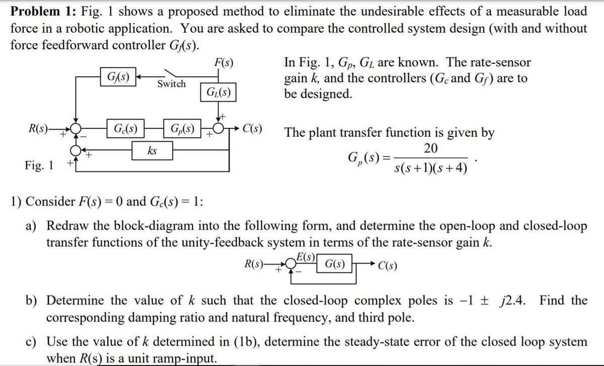
Transcribed Image Text:Problem 1: Fig. 1 shows a proposed method to eliminate the undesirable effects of a measurable load
force in a robotic application. You are asked to compare the controlled system design (with and without
force feedforward controller G(s).
In Fig. 1, Gp, GL are known. The rate-sensor
gain k, and the controllers (Go and Gf) are to
be designed.
F(s)
GAs)
Switch
GL(s)
R(s)
G(s)
G,(s)
C(s)
The plant transfer function is given by
ks
20
G,(s) =
Fig. 1
s(s+1)(s+4)
1) Consider F(s) = 0 and G(s) = 1:
a) Redraw the block-diagram into the following form, and determine the open-loop and closed-loop
transfer functions of the unity-feedback system in terms of the rate-sensor gain k.
E(s)[
G(s)
R(s)-
C(s)
b) Determine the value of k such that the closed-loop complex poles is -1 t j2.4. Find the
corresponding damping ratio and natural frequency, and third pole.
c) Use the value of k determined in (1b), determine the steady-state error of the closed loop system
when R(s) is a unit ramp-input.
Expert Solution
This question has been solved!
Explore an expertly crafted, step-by-step solution for a thorough understanding of key concepts.

This is a popular solution!

Trending now
This is a popular solution!

Step by step
Solved in 7 steps with 7 images

Recommended textbooks for you
Introductory Circuit Analysis (13th Edition)
Electrical Engineering
ISBN:
9780133923605
Author:
Robert L. Boylestad
Publisher:
PEARSON

Delmar's Standard Textbook Of Electricity
Electrical Engineering
ISBN:
9781337900348
Author:
Stephen L. Herman
Publisher:
Cengage Learning

Programmable Logic Controllers
Electrical Engineering
ISBN:
9780073373843
Author:
Frank D. Petruzella
Publisher:
McGraw-Hill Education
Introductory Circuit Analysis (13th Edition)
Electrical Engineering
ISBN:
9780133923605
Author:
Robert L. Boylestad
Publisher:
PEARSON
Delmar's Standard Textbook Of Electricity
Electrical Engineering
ISBN:
9781337900348
Author:
Stephen L. Herman
Publisher:
Cengage Learning
Programmable Logic Controllers
Electrical Engineering
ISBN:
9780073373843
Author:
Frank D. Petruzella
Publisher:
McGraw-Hill Education

Fundamentals of Electric Circuits
Electrical Engineering
ISBN:
9780078028229
Author:
Charles K Alexander, Matthew Sadiku
Publisher:
McGraw-Hill Education

Electric Circuits. (11th Edition)
Electrical Engineering
ISBN:
9780134746968
Author:
James W. Nilsson, Susan Riedel
Publisher:
PEARSON

Engineering Electromagnetics
Electrical Engineering
ISBN:
9780078028151
Author:
Hayt, William H. (william Hart), Jr, BUCK, John A.
Publisher:
Mcgraw-hill Education,