Problem 1 ( forces of 1.5 kd 3.0 kN at points B and C respectively. The cross section of the beam is The simply supported beam shown below is subjected to two concentrated rectangular with a width of 48 mm and a height of 72 mm. The side view showing the cross section is also illustrated below. 1- Draw the shear force and moment diagrams of the beam. From the diagrams, determine the magnitude and location of the maximum bending moment and the maximum transverse shearing force. 2- Determine the moment of inertia of the cross section about the bending axis (neutral axis) 3- Calculate the maximum tensile and compressive stresses in the beam. 1.5 m 1.5 kN B 1.5 m 3.0 kN C 1.5 m 48 mm -TE I 72 mm
Problem 1 ( forces of 1.5 kd 3.0 kN at points B and C respectively. The cross section of the beam is The simply supported beam shown below is subjected to two concentrated rectangular with a width of 48 mm and a height of 72 mm. The side view showing the cross section is also illustrated below. 1- Draw the shear force and moment diagrams of the beam. From the diagrams, determine the magnitude and location of the maximum bending moment and the maximum transverse shearing force. 2- Determine the moment of inertia of the cross section about the bending axis (neutral axis) 3- Calculate the maximum tensile and compressive stresses in the beam. 1.5 m 1.5 kN B 1.5 m 3.0 kN C 1.5 m 48 mm -TE I 72 mm

International Edition---engineering Mechanics: Statics, 4th Edition
4th Edition
ISBN:9781305501607
Author:Andrew Pytel And Jaan Kiusalaas
Publisher:Andrew Pytel And Jaan Kiusalaas
Chapter6: Beams And Cables
Section: Chapter Questions
Problem 6.42P: For the beam AB shown in Cases 1 and 2, derive and plot expressions for the shear force and bending...

Related questions

Question
Transcribed Image Text:Problem 1 (
forces of 1.5 kid 3.0 kN at points B and C respectively. The cross section of the beam is
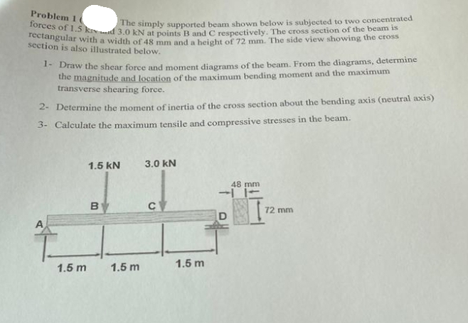
The simply supported beam shown below is subjected to two concentrated
rectangular with a width of 48 mm and a height of 72 mm. The side view showing the cross
section is also illustrated below.
1- Draw the shear force and moment diagrams of the beam. From the diagrams, determine
the magnitude and location of the maximum bending moment and the maximum
transverse shearing force.
2- Determine the moment of inertia of the cross section about the bending axis (neutral axis)
3- Calculate the maximum tensile and compressive stresses in the beam.
A
1.5 m
1.5 KN
B
1.5 m
3.0 kN
с
1.5 m
48 mm
72 mm
Expert Solution
This question has been solved!
Explore an expertly crafted, step-by-step solution for a thorough understanding of key concepts.

Step by step
Solved in 5 steps with 9 images

Knowledge Booster


Learn more about
Need a deep-dive on the concept behind this application? Look no further. Learn more about this topic, mechanical-engineering and related others by exploring similar questions and additional content below.Recommended textbooks for you
International Edition---engineering Mechanics: St…
Mechanical Engineering
ISBN:
9781305501607
Author:
Andrew Pytel And Jaan Kiusalaas
Publisher:
CENGAGE L
International Edition---engineering Mechanics: St…
Mechanical Engineering
ISBN:
9781305501607
Author:
Andrew Pytel And Jaan Kiusalaas
Publisher:
CENGAGE L