Problem 1 of 1: Determine the nodal solution and maximum 70 Iblin bending moment in the beam, if E = 28x10° psi and /= 24 in over the entire beam. Use 2 finite elements. 12 ft Solution:
Problem 1 of 1: Determine the nodal solution and maximum 70 Iblin bending moment in the beam, if E = 28x10° psi and /= 24 in over the entire beam. Use 2 finite elements. 12 ft Solution:

Mechanics of Materials (MindTap Course List)
9th Edition
ISBN:9781337093347
Author:Barry J. Goodno, James M. Gere
Publisher:Barry J. Goodno, James M. Gere
Chapter10: Statically Indeterminate Beams
Section: Chapter Questions
Problem 10.4.2P: A fixed-end beam AB carries point load P acting at point C. The beam has a rectangular cross section...

Related questions
Question
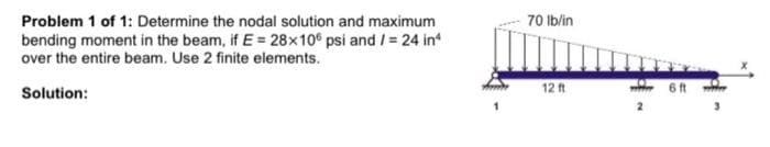
Transcribed Image Text:Problem 1 of 1: Determine the nodal solution and maximum
bending moment in the beam, if E = 28x10° psi and /= 24 in
over the entire beam. Use 2 finite elements.
70 Ib/in
Solution:
12 ft
6 ft
Expert Solution
This question has been solved!
Explore an expertly crafted, step-by-step solution for a thorough understanding of key concepts.

This is a popular solution!

Trending now
This is a popular solution!

Step by step
Solved in 3 steps with 5 images

Knowledge Booster


Learn more about
Need a deep-dive on the concept behind this application? Look no further. Learn more about this topic, mechanical-engineering and related others by exploring similar questions and additional content below.Recommended textbooks for you
Mechanics of Materials (MindTap Course List)
Mechanical Engineering
ISBN:
9781337093347
Author:
Barry J. Goodno, James M. Gere
Publisher:
Cengage Learning
Mechanics of Materials (MindTap Course List)
Mechanical Engineering
ISBN:
9781337093347
Author:
Barry J. Goodno, James M. Gere
Publisher:
Cengage Learning