A simply supported beam of length 4 m, is subjected to an Uniformly distributed load of 22 kN/m for entire span. has a hollow rectangular cross section of outer width 45 mm and outer depth of 90 mm with the wall thickness of 3mm. Find (i) The maximum bending moment, (ii)Bending stress induced, (iii) Radius of curvature, (iv) Flexural rigidity. Take E as 150 GPa. The maximum bending moment (in Nm) = Maximum Bending stress induced (in MPa) = Radius of curvature (in m) = Flexural Rigidity of the beam (in Nm2) :
A simply supported beam of length 4 m, is subjected to an Uniformly distributed load of 22 kN/m for entire span. has a hollow rectangular cross section of outer width 45 mm and outer depth of 90 mm with the wall thickness of 3mm. Find (i) The maximum bending moment, (ii)Bending stress induced, (iii) Radius of curvature, (iv) Flexural rigidity. Take E as 150 GPa. The maximum bending moment (in Nm) = Maximum Bending stress induced (in MPa) = Radius of curvature (in m) = Flexural Rigidity of the beam (in Nm2) :

Mechanics of Materials (MindTap Course List)
9th Edition
ISBN:9781337093347
Author:Barry J. Goodno, James M. Gere
Publisher:Barry J. Goodno, James M. Gere
Chapter5: Stresses In Beams (basic Topics)
Section: Chapter Questions
Problem 5.13.4P: A rectangular beam with semicircular notches, as shown in part b of the figure, has dimensions h =...

Related questions
Question
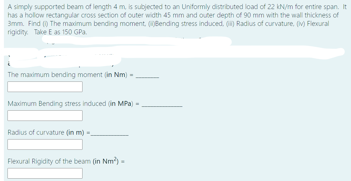
Transcribed Image Text:A simply supported beam of length 4 m, is subjected to an Uniformly distributed load of 22 kN/m for entire span. It
has a hollow rectangular cross section of outer width 45 mm and outer depth of 90 mm with the wall thickness of
3mm. Find (i) The maximum bending moment, (ii)Bending stress induced, (iii) Radius of curvature, (iv) Flexural
rigidity. Take E as 150 GPa.
The maximum bending moment (in Nm) =
Maximum Bending stress induced (in MPa) =
Radius of curvature (in m) =.
Flexural Rigidity of the beam (in Nm2) =
Expert Solution
This question has been solved!
Explore an expertly crafted, step-by-step solution for a thorough understanding of key concepts.

Step by step
Solved in 3 steps

Knowledge Booster


Learn more about
Need a deep-dive on the concept behind this application? Look no further. Learn more about this topic, mechanical-engineering and related others by exploring similar questions and additional content below.Recommended textbooks for you
Mechanics of Materials (MindTap Course List)
Mechanical Engineering
ISBN:
9781337093347
Author:
Barry J. Goodno, James M. Gere
Publisher:
Cengage Learning
Mechanics of Materials (MindTap Course List)
Mechanical Engineering
ISBN:
9781337093347
Author:
Barry J. Goodno, James M. Gere
Publisher:
Cengage Learning