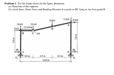
Problem 1. For the frame shown in the figure, determine (a) Reactions at the supports (b) Axial force, Shear Force and Bending Moment at a point on BC lying at Im from point B I5 KN 10AN 30 AN 10AN 10 KN 25 kN 12 KN/m 3 KN D B c pin H. 4.5 m 12.0 m 3.0m 4.5 m 5.0 m 7.0 m


Q: C: For truss shown in figure, determine the value of the forces in members AB and HB if P is 10 kN.…
A: Mechanical Equilibrium: A body is said to be in mechanical equilibrium if it satisfies the following…
Q: 7. The beam ABC, built into the wall at A and supported by a cable at C, carries a distributed load…
A:
Q: 7. The horizontal stick of length, L, shown in the figure is uniform and weighs tensions, T1 and T2,…
A: given:W=500Nweight of stick=200N
Q: The simple truss is loaded by a system of forces as shown in the figure. The truss is supported by a…
A: The free body diagram of the joint A is as follows: Calculate the vertical forces in the above…
Q: PROBLEM 2: Referring to the figure below, (a) draw the free body diagram of the bar AB (SO1.1), (b)…
A:
Q: Q.1) For the frame shown in figure, determine the horizontal and vertical components of 6 cm -9…
A: According to the information we have reaction pin at A, B, D, and roller E for the vertical and…
Q: Problem 2. For the Plane frame shown in figure, determine the axial force in cord (DE) and the…
A:
Q: Example -7: The uniform smooth rod shown in Fig. is subjected to a force and couple moment. If the…
A:
Q: Calculate the horizontal reaction at the hinge support A of the equilibrium rigid body shown in the…
A: The free body diagram of the beam is a follows:
Q: Question 1: Determine the support reactions at A and B and the reaction forces at hinge G for the…
A:
Q: The bell crank, which is in equilibrium under the forces shown in the figure, is supported by a…
A:
Q: A frame of two members (AC) and (BD) are connected together at pin B. The other ends are…
A:
Q: For the truss in the figure below, if P = 7 kN, what is the force in member DC? -3 m-3 m-3 m- F E VP…
A: Given data P=7 kN
Q: A frame of two members (AC) and (BD) are connected together at pin B. The other ends are…
A: Given Data Horizontal force on member AC at point C is :F=500 N
Q: The truss is subjected to the system of forces as shown in the following figure. The truss is…
A:
Q: SITUATION 2 A riveted bracket show in the figure is subjected to load P acting at an angle of e from…
A:
Q: For the given loads w = 28 KN/m and M=70 KN.m is supported as shown by a roller at D and a hinge at…
A: UDL is referred to uniformly distributed load (magnitude of load remains constant over a span of…
Q: The truss is subjected to the system of forces as shown in the following figure. The truss is…
A: Given data :- At A = 6 KN At E = 8 KN Find :- The force in Member AE = ?
Q: A frame of two members (AC) and (BD) are connected together at pin B. The other ends are…
A: Option a is correct.
Q: A frame of two members (AC) and (BD) are connected together at pin B. The other ends are…
A:
Q: Statics
A:
Q: The truss is subjected to the system of forces as shown in the following figure. The truss is…
A:
Q: 1. Calculate the support reactions, calculate internal forces on the designated section C, and plot…
A: as per our guidelines . i am giving the answer of 1st question. if you want to know the solution of…
Q: The simple truss is loaded by a system of forces as shown in the figure. The truss is supported by a…
A:
Q: Problem 2 1800 kN/m 600 kN/m The member BC is subjected to the distributed load as shown in the…
A:
Q: Ok A 30k 20 k 20 k 20 k 30k 30 ft- 30 ft 30 ft- 30 ft
A:
Q: D{ C l 5) The box truss shown in the figure is loaded by three vertical forces acting at joints A,…
A:
Q: a) What is a truss? Explain shortly in your own words, and illustrate with one example. b) For the…
A:
Q: Activity 1. For the truss shown in the figure, determine the forces acting on members AB, AC,BC,CE…
A: Given, The lengths, AC=1.5 mAE=1.5 mAG=4.5 mAH=6 mDE=2 m
Q: The truss is subjected to the system of forces as shown in the following figure. The truss is…
A:
Q: The simple truss is loaded by a system of forces as shown in the figure. The truss is supported by a…
A:
Q: 15 kN 5 kN/m The simply supported beam with a distributed load and couple moment at its center as…
A:
Q: A W410 x 60 standard steel shape is used to support the loads shown on the beam in the figure below.…
A: For solution refer below images.
Q: A steel plate, connected to a fixed channel using three identical bolts A, B and C, carries a load…
A: As per given question Load =6 kn We have to determine magnitude of resultant force
Q: Problem 2. For the Plane frame shown in figure, determine the axial force in cord (DE) and the…
A:
Q: 7. The beam ABC, built into the wall at A and supported by a cable at C, carries a distributed load…
A:
Q: Situation 8- The beam is supported at A and supported by a cable at B as shown in Figure AP-4.20.…
A: Calculate the point load due to uniformly varying load as follows: 12×2 m×800 N/m=800 N The distance…
Q: L/2 L/2 L/4 F F A cantilever beam of length L=3 m with a rigid extended rod of length L/4 welded at…
A: Given Beam is Data is, L= 3m, F= 5.15KN and θ=600 Free body diagram of beam. Let RAV=Vertical…
Q: members BD,CD & ED of the truss shown in Figure using method of section. 59.15, 8.34KN, 45.5 None of…
A:
Q: -1.5 m 10 kN- 1 m E 1 m D. 3D 1 m A B
A:
Q: 2) For the Simply Supported Beam Carrying Four point loads, as shown in the Figure, (a)…
A:
Q: Given: The truss shown in the figure below. Find: The values (kips) of the reactions at A and H.…
A:
Q: Q.6. For the frame shown in figure, determine the horizontal and vertical components of the pin B…
A:
Q: Problem 2. For the Plane frame shown in figure, determine the axial force in cord (DE) and the…
A: Moment (M) at point D: 29 kN.m Vertical Load at D: 7 kN Horizontal load on member BE: 10.5 kN
Q: For the loaded truss shown in the figure below and using the method of sections, 1) Determine the…
A: Given: Load, P = 1.7 kN To analyze the truss by method of sections, we assume a section X-X cutting…
Q: The truss is subjected to the system of forces as shown in the following figure. The truss is…
A: Given data The truss is subjected to the system of forces as shown in the following figure. The…
Q: (2) Draw the shear force and bending moment diagrams for the beam ABCD shown in the figure below.…
A:
Q: A frame of two members (AC) and (BD) are connected together at pin 8. The other ends are…
A: Free Body Diagram
Q: 12 kN 12 kN VE G Ag For the truss shown below, what are the reaction forces at supports? 1.8 m Bo D…
A: FBD of the system is,

Step by step
Solved in 3 steps with 2 images

- The cross section of a narrow-gage railway bridge is shown in part a of the figure. The bridge is constructed with longitudinal steel grinders that support the wood cross ties. The bridge is constructed with longitudinal steel girders that support the wood cross ties. The girders are restrained against lateral buckling by diagonal bracing, as indicated by the dashed lines. The spacing of the girders is S1= 50 in. and the spacing of the rails is s2= 30 in. The load transmitted by each rail to a single tie is P = 1500 1b. The cross section of a tie, shown in part b of the figure, has a width b =5.0 in. and depth d. Determine the minimum value of d based upon an allowable bending stress of 1125 psi in the wood tie. (Disregard the weight of the tie itself.)A wood beam AB on simple supports with span length equal to 10 ft is subjected to a uniform load of intensity 125 lb/ft acting along the entire length of the beam, a concentrated load of magnitude 7500 lb acting at a point 3 ft from the right-hand support, and a moment at A of 18,500 ft-lb (sec figure). The allowable stresses in bending and shear, respectively, are 2250 psi and 160 psi. From the table in Appendix G, select the lightest beam that will support the loads (disregard the weight of the beam). Taking into account the weight of the beam (weight density = 35 lb/ft3), verify that the selected beam is satisfactory, or if it is not, select a new beam.The composite beam shown in the figure is simply supported and carries a total uniform load of 40 kN/m on a span length of 4.0 m. The beam is built of a southern pine wood member having cross-sectional dimensions of 150 mm × 250 mm and two brass plates of cross-sectional dimensions 30 mm × 150 mm. Determine the maximum stresses (7b and ctwin the brass and wood, respectively, if the moduli of elasticity are EB= % GPa and Ew= 14 GPa. (Disregard the weight of the beam.) Find the required thickness of the brass plates so that the plate and wood reach their allowable stress values of Eb= 70 MPa and t Ew= 8.5 MPa simultaneously under the maximum moment. What is the maximum moment?
- Solve the preceding problem using a W 310 x 129 section, L = 1.8 m, P = 9.5 kN, and or x= 60°. See Table F-l(b) of Appendix F For the dimensions and properties of the beam..17 A mountain-bike rider going uphill applies torque T = Fd(F = l5lb, d = 4 in.) to the end of the handlebars ABCD by pulling on the handlebar extenders DE. Consider the right half of the handlebar assembly only (assume the bars are fixed at the fork at A). Segments AB and CD are prismatic with lengths L, = 2 in.andL3 = 8.5 in, and with outer diameters and thicknesses d01 = 1.25 in. 101 = 0.125 in. and d03 = O.87in.,i03 = 0.ll5in, respectively as shown. Segment BC’ of length L, = 1.2 in. however. is tapered, and outer diameter and thickness vary linearly between dimensions at B and C. Consider torsion effects only. Assume G = 4000 ksi is constant. Derive an integral expression for the angle of twist of half of the handlebar tube when it is subjected to torque T = Fd acting at the end. Evaluate ‘b1-, for the given numerical1ues.A simply supported beam is subjected to a in early varying distributed load q(x)=xL with maximum intensity q0at B. The beam has a length L = 4 m and rectangular cross section with a width of 200 mm and height of 300 mm. Determine the maximum permissible value for the maximum intensity, q0, if the allowable normal stresses in tension and compression are 120 M Pa.
- The beam AB shown in the figure supports a uniform load of intensity 3000 N/m acting over half the length of the beam. The beam rests on a foundation that produces a uniformly distributed load over the entire length. Draw the shear-force and bending-moment diagrams for this beam. Repeat part (a) for the distributed load variation shown in Fig. b.The cross section of a composite beam made of aluminum and steel is shown in the figure. The moduli of elasticity are TA= 75 GPa and Es= 200 GPa. Under the action of a bending moment that produces a maximum stress of 50 M Pa in the aluminum, what is the maximum stress xs in the steel? If the height of the beam remains at 120 mm and allowable stresses in steel and aluminum are defined as 94 M Pa and 40 M Pa, respectively, what heights h and h. arc required for aluminum and steel, respectively, so that both steel and aluminum reach their allowable stress values under the maximum moment?A wood beam reinforced by an aluminum channel section is shown in the figure. The beam has a cross section of dimensions 150 mm x 250 mm, and the channel has a uniform thickness of 6.5 mm. If the allowable stresses in the wood and aluminum are 8 M Pa and 38 M Pa, respectively, and if their moduli of elasticity are in the ratio 1 to 6, what is the maximum allowable bending moment for the beam?
- Determine the fixed-end moments (MAand MB) and fixed-end forces (R4and Rs) for a beam of length L supporting a triangular load of maximum intensity q0(see figure). Then draw the shear-force and bending-moment diagrams, labeling all critical ordinates.A truss ABC supports a load W at joint B, as shown in the figure. The length L, of member Aß is fixed, but the length of strut BC varies as the angle is changed. Strut BC has a solid circular cross section. Joint B is restrained against displacement perpendicular to the plane of the truss. Assuming that collapse occurs by Etiler buckling of the strut determine the angle for minimum weight of the strut.The continuous frame ABC has a fixed support at A, a roller support at C, and a rigid corner connection at B (see figure). Members AB and BC each have length L and flexural rigidity EL. A horizontal force P acts at mid-height of member AB. Find all reactions of the frame. What is the largest bending moment Mmaxin the frame? Note: Disregard axial deformations in member AB and consider only the effects of bending.