Problem # 4 In the circuit shown below. Determine the following a. Vs (at the secondary) b. Vout (across RL) c. Vrip (ripple votage) d. VDC e. PIV (Peak Inverse Voltage) 10:1 Dy 1IS V ms Output D, 50 pF 22 M All diodes are IN4001. llele
Problem # 4 In the circuit shown below. Determine the following a. Vs (at the secondary) b. Vout (across RL) c. Vrip (ripple votage) d. VDC e. PIV (Peak Inverse Voltage) 10:1 Dy 1IS V ms Output D, 50 pF 22 M All diodes are IN4001. llele

Chapter59: Motor Startup And Troubleshooting Basics
Section: Chapter Questions
Problem 12SQ: How is a solid-state diode tested? Explain.

Related questions
Question
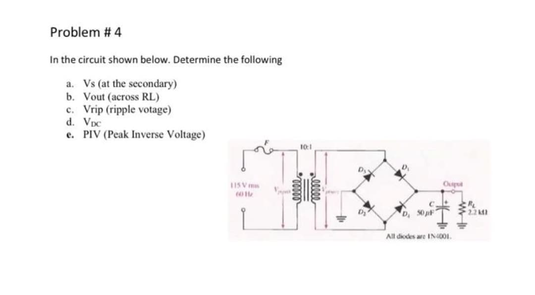
Transcribed Image Text:Problem # 4
In the circuit shown below. Determine the following
a. Vs (at the secondary)
b. Vout (across RL)
c. Vrip (ripple votage)
d. VpC
e. PIV (Peak Inverse Voltage)
10:1
Dy
1ISV ms
Ouiput
RL
2.2 k2
D, 50 pF
All diodes are IN4001.
alleee
Expert Solution
This question has been solved!
Explore an expertly crafted, step-by-step solution for a thorough understanding of key concepts.

Step by step
Solved in 6 steps

Recommended textbooks for you