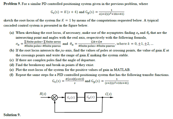
Problem 9. For a similar PD controlled positioning system given in the previous problem, where Ge(s) = K(s + 4) and Gp(s) = s(s+2)(s²+105+41) sketch the root-locus of the system for K = 1 by means of the computations requested below. A tyipical cascaded control system is presented in the figure below. (a) When sketching the root locus, if necessary, make use of the asymptotes finding o, and 0, that are the intersecting point and angles with the real axis, respectively with the following formula, Efinite poles-E finite zeros #finite poles-#finite pzeros (2k+1)m #finite poles-#finite pzeros and Oa ,where k = 0,±1,±2, .. (b) If the root locus intersects the jo-axis, find the values of poles at crossing points, the value of gain K at the crossings points and write the range of gain K making the system stable. (c) If there are complex poles find the angle of departure. (d) Find the breakaway and break-in points if they exist. (e) Plot the root-locus of the system for the positive values of gain in MATLAB. (f) Repeat the same steps for a PID controlled positioning system that has the following transfer functions. Ge(s) = K(s+4)(s+0.5) and Gp(s) = 1 (s+2)(s²+10s+41) R(s) (s) | G(s) Gp(s) Solution 9.
Problem 9. For a similar PD controlled positioning system given in the previous problem, where Ge(s) = K(s + 4) and Gp(s) = s(s+2)(s²+105+41) sketch the root-locus of the system for K = 1 by means of the computations requested below. A tyipical cascaded control system is presented in the figure below. (a) When sketching the root locus, if necessary, make use of the asymptotes finding o, and 0, that are the intersecting point and angles with the real axis, respectively with the following formula, Efinite poles-E finite zeros #finite poles-#finite pzeros (2k+1)m #finite poles-#finite pzeros and Oa ,where k = 0,±1,±2, .. (b) If the root locus intersects the jo-axis, find the values of poles at crossing points, the value of gain K at the crossings points and write the range of gain K making the system stable. (c) If there are complex poles find the angle of departure. (d) Find the breakaway and break-in points if they exist. (e) Plot the root-locus of the system for the positive values of gain in MATLAB. (f) Repeat the same steps for a PID controlled positioning system that has the following transfer functions. Ge(s) = K(s+4)(s+0.5) and Gp(s) = 1 (s+2)(s²+10s+41) R(s) (s) | G(s) Gp(s) Solution 9.

Introductory Circuit Analysis (13th Edition)
13th Edition
ISBN:9780133923605
Author:Robert L. Boylestad
Publisher:Robert L. Boylestad
Chapter1: Introduction
Section: Chapter Questions
Problem 1P: Visit your local library (at school or home) and describe the extent to which it provides literature...

Related questions
Question
TRY TO SOLVE IT AS A TEXT NOT HANDWRITTING PLEASE
Transcribed Image Text:Problem 9. For a similar PD controlled positioning system given in the previous problem, where
Ge(s) = K(s + 4) and Gp(s) =
s(s+2)(s²+105+41)
sketch the root-locus of the system for K = 1 by means of the computations requested below. A tyipical
cascaded control system is presented in the figure below.
(a) When sketching the root locus, if necessary, make use of the asymptotes finding oa and O, that are the
intersecting point and angles with the real axis, respectively with the following formula,
Efinite poles-E finite zeros
#finite poles-#finite pzeros
(2k+1)m
#finite poles-#finite pzeros
and Oa
,where k = 0,±1,±2, ..
(b) If the root locus intersects the jw-axis, find the values of poles at crossing points, the value of gain K at
the crossings points and write the range of gain K making the system stable.
(c) If there are complex poles find the angle of departure.
(d) Find the breakaway and break-in points if they exist.
(e) Plot the root-locus of the system for the positive values of gain in MATLAB.
(f) Repeat the same steps for a PID controlled positioning system that has the following transfer functions.
Ge(s) = K(s+4)(s+0.5)
and Gp(s) =
1
(s+2)(s²+10s+41)
R(s)
(s)
| G(s)
Gp(s)
Solution 9.
Expert Solution
This question has been solved!
Explore an expertly crafted, step-by-step solution for a thorough understanding of key concepts.

Step by step
Solved in 8 steps with 7 images

Knowledge Booster

![Digital Modulation Scheme (Amplitude-Shift Keying [ASK], Phase-Shift Keying [PSK], Frequency-Shift Keying [FSK])](/static/compass_v2/subjects/engineering/electrical-engineering.svg)
Learn more about
Need a deep-dive on the concept behind this application? Look no further. Learn more about this topic, electrical-engineering and related others by exploring similar questions and additional content below.Recommended textbooks for you
Introductory Circuit Analysis (13th Edition)
Electrical Engineering
ISBN:
9780133923605
Author:
Robert L. Boylestad
Publisher:
PEARSON

Delmar's Standard Textbook Of Electricity
Electrical Engineering
ISBN:
9781337900348
Author:
Stephen L. Herman
Publisher:
Cengage Learning

Programmable Logic Controllers
Electrical Engineering
ISBN:
9780073373843
Author:
Frank D. Petruzella
Publisher:
McGraw-Hill Education
Introductory Circuit Analysis (13th Edition)
Electrical Engineering
ISBN:
9780133923605
Author:
Robert L. Boylestad
Publisher:
PEARSON
Delmar's Standard Textbook Of Electricity
Electrical Engineering
ISBN:
9781337900348
Author:
Stephen L. Herman
Publisher:
Cengage Learning
Programmable Logic Controllers
Electrical Engineering
ISBN:
9780073373843
Author:
Frank D. Petruzella
Publisher:
McGraw-Hill Education

Fundamentals of Electric Circuits
Electrical Engineering
ISBN:
9780078028229
Author:
Charles K Alexander, Matthew Sadiku
Publisher:
McGraw-Hill Education

Electric Circuits. (11th Edition)
Electrical Engineering
ISBN:
9780134746968
Author:
James W. Nilsson, Susan Riedel
Publisher:
PEARSON

Engineering Electromagnetics
Electrical Engineering
ISBN:
9780078028151
Author:
Hayt, William H. (william Hart), Jr, BUCK, John A.
Publisher:
Mcgraw-hill Education,