PROBLEMS 5.1 The elements of the buck-boost converter of Fig. 5.21 are ideal: all losses may be ignored. Your results for parts (a) and (b) should agree with Table 5.2. D, C R V Fig. 5.21 Buck-boost vonverter of Problems 5.1 and 5.13. Show that the converter operates in discontinuous conduction mode when K < K.v and derive expressions for K and K Derive an expression for the de conversion ratio V/V, of the buck-boost converter operating in discontinuous conduction mode. (a) (b) (c) For K = 0.1, plot V/v, over the entire range 0 sDS I.
PROBLEMS 5.1 The elements of the buck-boost converter of Fig. 5.21 are ideal: all losses may be ignored. Your results for parts (a) and (b) should agree with Table 5.2. D, C R V Fig. 5.21 Buck-boost vonverter of Problems 5.1 and 5.13. Show that the converter operates in discontinuous conduction mode when K < K.v and derive expressions for K and K Derive an expression for the de conversion ratio V/V, of the buck-boost converter operating in discontinuous conduction mode. (a) (b) (c) For K = 0.1, plot V/v, over the entire range 0 sDS I.

Introductory Circuit Analysis (13th Edition)
13th Edition
ISBN:9780133923605
Author:Robert L. Boylestad
Publisher:Robert L. Boylestad
Chapter1: Introduction
Section: Chapter Questions
Problem 1P: Visit your local library (at school or home) and describe the extent to which it provides literature...

Related questions
Question
Transcribed Image Text:PROBLEMS
5.1
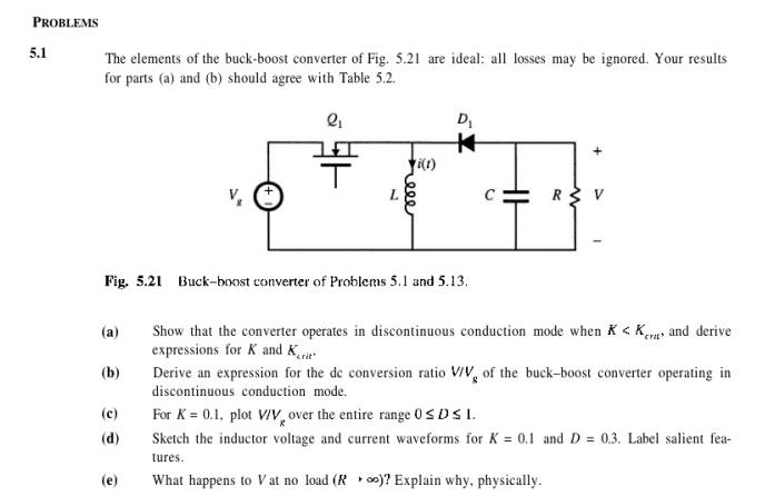
The elements of the buck-boost converter of Fig. 5.21 are ideal: all losses may be ignored. Your results
for parts (a) and (b) should agree with Table 5.2.
D,
C
R V
Fig. 5.21 Buck-boost converter of Problems 5.1 and 5.13.
Show that the converter operates in discontinuous conduction mode when K < Ka and derive
expressions for K and K
Derive an expression for the de conversion ratio ViV, of the buck-boost converter operating in
(a)
(b)
discontinuous conduction mode.
(c)
For K = 0.1, plot V/v, over the entire range 0 SDSI.
(d)
Sketch the inductor voltage and current waveforms for K = 0.1 and D = 0.3. Label salient fea-
tures.
(e)
What happens to V at no load (R » )? Explain why, physically.
Expert Solution
This question has been solved!
Explore an expertly crafted, step-by-step solution for a thorough understanding of key concepts.

This is a popular solution!

Trending now
This is a popular solution!

Step by step
Solved in 4 steps with 3 images

Recommended textbooks for you
Introductory Circuit Analysis (13th Edition)
Electrical Engineering
ISBN:
9780133923605
Author:
Robert L. Boylestad
Publisher:
PEARSON

Delmar's Standard Textbook Of Electricity
Electrical Engineering
ISBN:
9781337900348
Author:
Stephen L. Herman
Publisher:
Cengage Learning

Programmable Logic Controllers
Electrical Engineering
ISBN:
9780073373843
Author:
Frank D. Petruzella
Publisher:
McGraw-Hill Education
Introductory Circuit Analysis (13th Edition)
Electrical Engineering
ISBN:
9780133923605
Author:
Robert L. Boylestad
Publisher:
PEARSON
Delmar's Standard Textbook Of Electricity
Electrical Engineering
ISBN:
9781337900348
Author:
Stephen L. Herman
Publisher:
Cengage Learning
Programmable Logic Controllers
Electrical Engineering
ISBN:
9780073373843
Author:
Frank D. Petruzella
Publisher:
McGraw-Hill Education

Fundamentals of Electric Circuits
Electrical Engineering
ISBN:
9780078028229
Author:
Charles K Alexander, Matthew Sadiku
Publisher:
McGraw-Hill Education

Electric Circuits. (11th Edition)
Electrical Engineering
ISBN:
9780134746968
Author:
James W. Nilsson, Susan Riedel
Publisher:
PEARSON

Engineering Electromagnetics
Electrical Engineering
ISBN:
9780078028151
Author:
Hayt, William H. (william Hart), Jr, BUCK, John A.
Publisher:
Mcgraw-hill Education,