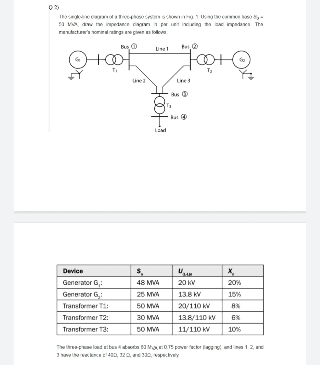
Q 2) The single-line diagram of a three-phase system is shown in Fig. 1. Using the common base Sp = 50 MVA, draw the impedance diagram in per unit including the load impedance. The manufacturer's nominal ratings are given as follows: Bus O Bus 2 Line 1 T1 T2 Line 2 Line 3 Bus 3 T3 Bus 4 Load Device Generator G,: 48 MVA 20 kV 20% Generator G,: 25 MVA 13.8 kV 15% Transformer T1: 50 MVA 20/110 kV 8% Transformer T2: 30 MVA 13.8/110 kV 6% Transformer T3: 50 MVA 11/110 kV 10% The three-phase load at bus 4 absorbs 60 MVA at 0.75 power factor (lagging), and lines 1, 2, and 3 have the reactance of 400, 32 0, and 300, respectively.
Q 2) The single-line diagram of a three-phase system is shown in Fig. 1. Using the common base Sp = 50 MVA, draw the impedance diagram in per unit including the load impedance. The manufacturer's nominal ratings are given as follows: Bus O Bus 2 Line 1 T1 T2 Line 2 Line 3 Bus 3 T3 Bus 4 Load Device Generator G,: 48 MVA 20 kV 20% Generator G,: 25 MVA 13.8 kV 15% Transformer T1: 50 MVA 20/110 kV 8% Transformer T2: 30 MVA 13.8/110 kV 6% Transformer T3: 50 MVA 11/110 kV 10% The three-phase load at bus 4 absorbs 60 MVA at 0.75 power factor (lagging), and lines 1, 2, and 3 have the reactance of 400, 32 0, and 300, respectively.

Power System Analysis and Design (MindTap Course List)
6th Edition
ISBN:9781305632134
Author:J. Duncan Glover, Thomas Overbye, Mulukutla S. Sarma
Publisher:J. Duncan Glover, Thomas Overbye, Mulukutla S. Sarma
Chapter2: Fundamentals
Section: Chapter Questions
Problem 2.44P: Two balanced three-phase loads that are connected in parallel are fed by a three-phase line having a...

Related questions

Question
Subject Power System Analysis
Transcribed Image Text:Q 2)
The single-line diagram of a three-phase system is shown in Fig. 1. Using the common base Sp =
50 MVA, draw the impedance diagram in per unit including the load impedance. The
manufacturer's nominal ratings are given as follows:
Bus 0
Bus 2
Line 1
G2
T2
Line 2
Line 3
Bus 3
T3
Bus 4
Load
Device
S.
Generator G,:
48 MVA
20 kV
20%
Generator G,:
25 MVA
13.8 kV
15%
Transformer T1:
50 MVA
20/110 kV
8%
Transformer T2:
30 MVA
13.8/110 kV
6%
Transformer T3:
50 MVA
11/110 kV
10%
The three-phase load at bus 4 absorbs 60 MyA at 0.75 power factor (lagging), and lines 1, 2, and
3 have the reactance of 402, 32 Q, and 300, respectively.
Expert Solution
This question has been solved!
Explore an expertly crafted, step-by-step solution for a thorough understanding of key concepts.

This is a popular solution!

Trending now
This is a popular solution!

Step by step
Solved in 3 steps with 3 images

Knowledge Booster


Learn more about
Need a deep-dive on the concept behind this application? Look no further. Learn more about this topic, electrical-engineering and related others by exploring similar questions and additional content below.Recommended textbooks for you
Power System Analysis and Design (MindTap Course …
Electrical Engineering
ISBN:
9781305632134
Author:
J. Duncan Glover, Thomas Overbye, Mulukutla S. Sarma
Publisher:
Cengage Learning
Power System Analysis and Design (MindTap Course …
Electrical Engineering
ISBN:
9781305632134
Author:
J. Duncan Glover, Thomas Overbye, Mulukutla S. Sarma
Publisher:
Cengage Learning