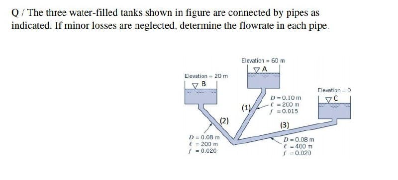
Q/ The three water-filled tanks shown in figure are connected by pipes as indicated. If minor losses are neglected, determine the flowrate in each pipe.
Q: Assignment 4 For the system shown, What is the flow direction? b. What kind of machine is at A? c Do…
A: Given Data **As per our company policy we are supposed to do only 3 subpart if you need the rest…
Q: asoline at 77°F flows from a pressurized upper tank to a vented lower tank as shown in the figure…
A: Givenh2=52.8ftTemp=77°Fρgasoline=45lb/ft3
Q: The figure shows a siphon discharging oil (sp.gr.0.90). The siphon is composed of 75 mm followed by…
A:
Q: Q1/ Neglecting losses, determine the discharge in Fig. below
A: Given data: The diameter of the small cavity, d = 4 in. The specific gravity of oil, SGoil = 0.75.…
Q: Determine the direction of flow through the tube shown in Fig. 4, in which y 50 ib/ft', u = 0.40 p .…
A:
Q: A pipe 800 m long connects two reservoirs whose level difference is 60 m. Find the discharge in pipe…
A:
Q: Calculate the discharge through the pipe line shown in figure. Also find the pressure at point A and…
A: The density of water is 1000 kg/m3. The atmospheric pressure is 101325 Pa.
Q: Give the classification of flow meters
A: Flow meters can be classified into two categories - Mass flow meters Volume flow meters
Q: A horizontal 154 mm diameter pipe gradually reduces its section to 53 diameter, subsequently…
A: Pipe diameter at the inlet, d1=154 mm=0.154 mPipe diameter at the section 2, d2=53 mm =0.053…
Q: The discharge of water of a looping pipe system is shown, compute the Head-loss and the division of…
A:
Q: The pump in figure 3 delivers water from the reservoir to the nozzle at the rate of 0.13 m/s. The…
A:
Q: Petrol is drained from a tank X to tank Y via pipeline A-B (see figure Q3). A pump is then used to…
A:
Q: 1- Derive an expression for the flow rate q over the spillway shown in figure bellow per foot of…
A:
Q: Q5:- Calculate the discharge of the system in fig. (4),neglecting all losses except through the…
A:
Q: A pipe network consists of pipeline as shown. If the total rate of flow is 10 liters/sec, compute…
A: Total flow rate, Q1=10 liters/sec=0.010 m3/sd1=600 mm=0.6 mL1=3000 mC1=110d2=300 mm=0.3 mL2=2200…
Q: Find the losses of head when a pipe diameter 200 mm is suddenly enlarged to diameter 400 mm. The…
A: In genuine fluid systems comprising liquids or gases, head loss is unavoidable.It is created by…
Q: Considering the figure to the right with flow from A to D, compute the total head loss from A to D…
A: As per the darcy weisbach equation we can say that Hf=flv22gd=flQ212.1 d5f = friction factorl =…
Q: Q1) Using a system similar to that shown in figure, if air pressure p = 50 kPa., and the depth h₁ =…
A:
Q: Q.3. Water (assumed inviscid and incompressible) flows 5"- steadily in the vertical variable-area…
A: Venturi-meter measures the flow rate of the flowing fluid. The discharge coefficient of…
Q: Water flows radially between the two flanges at the end of 0.2 m diameter pipe as shown in Fig.…
A:
Q: he figure shows a siphon discharging oil (sp.gr.= 0.90). The siphon is composed of 75 mm pipe…
A:
Q: Flow of water from a pipe connected to a tank is 10 m/s. Determine the height of the tank.
A:
Q: A pump has a brake horsepower of 39 hp with an efficiency of 81%. Neglecting frictional losses,…
A:
Q: a) Qualitatively sketch the Hydraulic Grade Line and the Energy Grade Line of the flow within the…
A:
Q: 05- The three water-filled tanks shown in Fig. are connected by pipes as indicated. If minor losses…
A: Assume the fluid flows room A to B and A to C . Q1=Q2+Q3or π40.12V1 = π40.082V2 + π40.082V3V1= 0.64…
Q: Q5) Using a system similar to that shown in figure, compute the required air pressure above the…
A: Given data h1 = 0.3 mh2 = 5 mWe have to find the air pressure required to cause the jet to rise to…
Q: A pipe network consists of pipeline as shown. If the total rate of flow is 10 liters/sec, compute…
A:
Q: A reservoir has a depth of 20 ft. A pipe at the base of the reservoir needs to convey discharge of 2…
A: Given data: A reservoir has depth h=20 ft Discharge…
Q: Q1: If flow rate in pipe shown is (0.5m'/s) find the (H). H. water D=300 mm
A: Given data Volume flow rate = Q = 0.5 m3/sDiameter of pipe = 300 mm = 0.3 m
Q: pipe with 20 mm diameter as shown in Figure Q3. If the pressure at point 1 is P1 kPa. Determine the…
A: since P1 value is not given then assume that P1= gauge pressure at point 1 in kpa. Take density of…
Q: Oil (SG = 0.84) is flowing in a pipe under the conditions shown in Figure. Find the pressure at…
A:
Q: O A horizontal pipe gradually reduces from 300 mm diameter section to 100 mm diameter section. The…
A:
Q: Problem 3: Water flows steadily through the large tanks shown in this figure. Determine the water…
A: Given Flow from bucket to bucket To find Depth of the bucket hA
Q: Part A - The three tanks shown in the figure below are connected by new cast iron pipes (ɛ = 0.26…
A:
Q: B-Draw the hydraulic gradient line and energy gradient line for the pipe system shown in figure…
A:
Q: 1. A siphon has an uniform circular section of 70 mm diameter and consists of a bent pipe with its…
A: for answers apply bernollis equation between A and C for Vc and for Pressure at B apply between A…
Q: 2. Oil flows through the system shown in figure below with negligible losses. Determine the…
A: Given data
Q: Q1: If flow rate in pipe shown is (0.5m/s) find the (H). H. water D=300 mm
A:
Q: How many liters per second of water must the pump shown supply when the flow needed in the 915-mm…
A:
Q: Water flows steadily through the elbow, placed horizontally on the surface shown in figure.…
A:
Q: Given the problem: a.) Express a pressure gage reading of 35 psi in absolute pascals. Assuming Patm…
A: a) gauge pressure is given , P= 35psi Patm=100 KPa
Q: Q4) The three water-filled tanks shown in Figure below are connected by pipes as indicated. If minor…
A:
Q: A pumped fluid distribution system is being designed to deliver 400 gal/min of water to a cooling…
A:
Q: Q1) Using a system similar to that shown in figure, compute the required air pressure above the…
A: Find the pressure in the tank.
Q: In the scheme presented in Figure shows that H is 12m. the losses located (smaller) are referring to…
A:
Q: Water at 50°F is pumped between two reservoirs at 0.2 ft/s through 400 ft of 2-in Schedule 40 steel…
A:
Q: The pump in figure 3 delivers water from the reservoir to the nozzle at the rate of 0.13 m/s. The…
A: Given The flow rate, Q = 0.13 m^3/s The head loss, h = 27.5 N.m/N The nozzle tip diameter, d = 0.074…
Q: Figure Q1 shows the sewage siphon which regulates the level of water in the large holding tank A.…
A:
Q: b) Draw the energy grade line (EGL) and the hydraulic grade line (HGL) for the flow in the following…
A:
Q: A 3' diameter ppe flows full when it carries 30 cfs. find the discharge and depth in the pipe if the…
A: Given data: The diameter of pipe D0 =3ft Full flow rate Q=30 cfs The velocity of flow at any depth…
Step by step
Solved in 2 steps with 5 images
- Find the pressure at point 2 given the isometric drawing of the commercial steel pipeline indicating the straight pipes length and with the following data below:Loss coefficients:• check valve, k = 5.0• gate valves, k = 0.20• elbows, k = 0.75• flowmeter, k = 13.0Pump flowrate = 10 m3/hrFluid power adding by pump = 3.7 HPPressure at point 1 = 60 kPagPipe inside diameter = 50mmViscosity = 0.17 Pa.sSpecific gravity = 0.89Pipe inside surface roughness = 0.00015 ft.For the pipe system shown. Assume n = 0.013 for all pipes. Neglect minor losses. 1. Compute the head loss from A to B in terms of Q. a. 0.056Q2 b. 0.029Q2 c. 0.016Q2 d. 0.096Q2 2. Assuming Q = 12 cfs, compute the head loss of pipe CD. a. 15.78 ft b. 13.02 ft c. 18.56 ft d. 24.56 ft 3. Assuming Q = 12 cfs, compute the total head loss from A to D. a. 47.786 ft b. 56.673 ft c. 89.451 ft d. 32.562 ftThis is a fluid machine question. Water reservoir is pumped over a hill through a pipe 450 mm in diameter and a pressure of 98.08 kPa is maintained in the summit water discharge is 30 m above the reservoir. The quantity pumped is 0.50 m3/s. rrictional losses in the discharge and suction pipe of the pump is equivalent to 1.5 m head loss. The speed of the pump is 800 rpm, what amount of energy must be furnished by the pump in kW?
- The following system is fed by a centrifugal pump. The piping is constructed from smooth plastic of OD 55 mm, wall thickness 2.5 mm. The minor losses for the system prior to the pump are given by KL = 12.0. The system curves for this pump are attached. If the flowrate is reduced to 1.4 m3/hr, and the upstream head requirement were 17 m, what would the electrical power requirement of the pump be?The system consists of 1200 m of 5 cm cast iron pipe, two 45° and four 90° flanged long-radius elbows, a fully open flanged globe valve, and a sharp exit into a reservoir. If the elevation at point 1 is 400 m, what gage pressure is required at point 1 to deliver 0.005 m3/s of water into the reservoir? Use the following: v = 1 x 10⁻⁶ m2/s Kentrance = 0.5 Kexit = 1 Kvalve = 6.9 f = 0.0316 γ = 9810 N/m3 Choices: 3.44 Mpa 1.02 MPa 3.48 Mpa 1.00 MPa None of the choices1. Bernoulli Equation on Pump: Water is being pumped from the lower reservoir to the upper reservoir, as shown in the figure. Water is being pumped from the lower reservoir to the upper reservoir, as shown in the figure. Determine the pump horsepower required, given the following data:Q = 23 ft3/sD = 24 in.Ηpump = 75 %Ltotal = 3600 fthpipe = head loss coefficient = 0.0076 ft/total pipeline length ft show Complete Solution/s (i.e. transformations, equivalent formula, etc).
- Water 60°F flows at 10 ft/s in a 3 in. diameter pipe that is 100 ft long. There are six elbows (KL = 1) and two gate valves (KL = 0.3). The end of the pipe is at elevation 20 ft above the inlet. The pressure at the inlet is 50 psia. The roughness height is 0.0002 ft. Determine the head at the inlet, head loss,pressure drop due to losses, and absolute pressure at the end. *Show your correct and complete solution. Please include schematic diagram and assumptions.*For the flow configuration shown, you are required to design a pump station to transfer water from the bottom tank to the upper tank. In your own words, explain the steps that are needed to be followed for the design of the pump system. Your answer should be typed and not more than one page. The pipe equivalent roughness is 1.5 mm. And a valve with a k=10 is located just upstream of the lower reservoir (other losses are negligible). Take p=1000 kg/m”, g = 9.81 m/s?, and u = 1.179 x 10² kg/m.s.As seen in Figure 3 below, the water from the tank 1 is pumped to the tank 2 with a flow rate of 5,664 liters/s, passing through a pipe with a diameter of 50.8 mm and a length of 121.92 m. Some of the local losses in the system are also shown on the figure. Calculate the effective power of the pump by taking the relative roughness ɛ / d = 0.001 Note: For all questions, pwater = 1000 kg/m³, g=9.81m/s^2 , the kinematic viscosity of water is 1.0219x10⁶ m²/s and the questions can be solved by accepting the values that are not given.
- Water at 38°C flows from A to B through 244 m of average 300-mm-I.D. cast iron pipe (∊ = 0.00061 m). Point B is 9.1 m above A, and the pressure at B must be maintained at 138 kPa. If 0.222 m3/s is to flow through the pipe, what must be the pressure at A?You are evaluating a pipe network transporting water from a large river reservoir to the citywater storage facility. According to the pipe specifications, the pressure leaving the pipe network(continuing to city storage) cannot exceed 3 psi. Given Qa, pipe diameters (Da – Dd), determinethe pressure exiting the pipe network. Do the city designers need to reconfigure the set-up. Usethe Hazen-Williams equation to determine the head losses. All pipe lengths are 200 feet long,and the pipes are made of recently installed galvanized iron. given below Flow rate and Diameter for all 4 pipes: Q_a=42 csf, D_a=4ft, D_b=3.2ft, D_c=7ft, D_d=2.1ft.Subject : Fluid mechanics Read the question carefully and give me right solution according to the question. Two pipes with C1 = 120, connected in series, discharge 4.75 cfs with a loss of head of 27 ft. Each pipe has a length of 1000 ft. If one pipe has a diameter of 18 inches, determine the diameter of the other pipe. Neglect minor losses. Note: Diagram not given