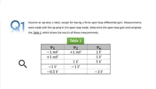
Q1 Assume an op-amp is ideal, except for having a finite open-loop differential gain. Measurements were made with the op-amp in the open-loop mode .Determine the open-loop gain and complete the Zable 1 which shows the results of those measurements. Table 1
Q: What must the voltage at the inverting input of the op- amp be? What is the voltage drop across Rin?…
A:
Q: Assuming the op-amp is ideal, what is the value of vo (in millivolts)?
A:
Q: 1. Describe some of the characteristics of a practical op-amp. 2. What does a differential amplifier…
A: We are authorized to answer one question at a time, since you have not mentioned which question you…
Q: What are the characteristics of an ideal op amp
A: The characteristics of ideal operational amplifier are as follows; The output impedance of ideal…
Q: Q2/B)- Show the connection of three combination op-amp stages ( Parallel and series connection)…
A:
Q: An amplifier of gain K and digital thermometer with gain Kr, are inserted into the loop as shown…
A: The given control system is shown below: It is given that: a=1b=3c=2d=4e=7
Q: Figure Q2(a) shows an amplifier system with the given input voltage waveform Vin and the…
A:
Q: Derive a mathematical expression to determine the stability factor for voltage – feedback bias…
A: The mathematical expression for stability factor for voltage-feedback bias circuit- so First we draw…
Q: For the feedback voltage amplifier of Figure (Q2), let the Op Amp have an infinite input resistance,…
A: Feedback Amplifier-Feedback amplifier is the process in which some part of the output to the input…
Q: For the ideal OP-Amp in negative feedback configuration shown in Figure Q30, calculate the…
A:
Q: Find out the voltage offset null circuit for the 741 op-amp?
A:
Q: Model a three op-amp instrumentation amplifier circuit with assumed values of resistors in which…
A: Most commonly used Instrumentation amplifiers consist of three op-amps. In this circuit, a…
Q: Determine the closed-loop gain of the ideal OP-AMP circuit given with the following parameters: R1 =…
A: We need to find out closed loop gain for given circuit
Q: 02 (B):- For the non-inverting operational amplifier circuit shown in Figure (3). 1) Derive the…
A:
Q: P2.24 A two-transistor series voltage feedback amplifier is shown in Figure P2.24(a). This AC…
A: Given: A two-transistor series voltage feedback amplifier is shown below: A block diagram…
Q: For the op-amp shown in the following figure, the unity-gain bandwidth has the value of 20.5 KHz.…
A:
Q: What are the nominal, minimum, and maximum values of the open-loop gain at 25◦C for an OP-27…
A: Given TA = 25◦ C, Supply voltage of the amplifier Calculating nominal value of the open loop gain
Q: 9. How do the open-loop voltage gain and the closed-loop voltage gain of an op-amp differ?
A: 9-The open-loop gain of the op-amp is the gain without the feedback path, it is the basic op-amp…
Q: 2. How will you convert any op-amp summing amplifier into a voltage averaging amplifier?
A: Since you have asked multiple questions, we will solve the first question for you. If you want any…
Q: Assuming the op amp to be ideal, derive an expression for the closed-loop gain of the circuit shown…
A:
Q: 4. What is the voltage gain of an inverting op-amp in which the feedback resistor has a value of…
A: Given data, An inverting op-amp in which Rf=7000 ΩRin=1500 Ω
Q: Explain how you would determine the gain of an op-amp circuit (shown below) from measurements.…
A: According to the question, Explain how you would determine the gain of an op-amp circuit (shown…
Q: show that drawing of the op amp differential gain configuration
A: The differential gain configuration of an Op-Amp includes two stages of input amplification. The…
Q: shown in Figure gain K. Consider the closed-loop system with transport lag .Determine the stability…
A: Given:
Q: A non-inverting op-amp circuit has the open loop gain of 104 and the resistances R1 = 2k Ω and R2 =…
A: Non Inverting Op-amp
Q: Draw a n-p-n transistor connected in circuit common base (CB). Draw the input current-voltage…
A:
Q: Q1) Compare the practical results and the theoretical results for the Inverting Op-Amp and also…
A: An OPAMP(operational amplifier) is an integrated electronic circuit that is used to amplify weak…
Q: C. Draw a n-p-n transistor connected in circuit common emitter (CE). Draw the input current-voltage…
A:
Q: (2-1) Assuming that the output is feeding a 20-k2 resistor, determine the total voltage gain and…
A: Given the circuit, as shown below: Assuming that the output is feeding a 20 kΩ, we need to…
Q: for the system shown in the block diagram of figure below determine the values of gain k1 and…
A: k1,k2=?Max. overshoot for unit step mp=e-πξ1-ξ2=0.25 (given)e-πξ1-ξ2=0.25Apply ln on both…
Q: When 100 V and 20 V are applied to the non inverting and the inverting terminal of open loop an…
A: For an open-loop operational amplifier, if Ad and Ac represents the differential gain and…
Q: Why is there a difference between the theoretical and practical values of voltage gain in an…
A: In most of the experiments there is a difference between theoretical and practical values of voltage…
Q: For an ideal op-amp, the open loop gain (Av) loop gain linear applications that must employ -ve…
A: Features of op-amp High CMRR High gain High input impedance Low output impedance
Q: A noninverting amplifier is being designed to have a closed-loop gain of 36 dB. What op-amp gain is…
A: Given: AvIdeal = 36 dB
Q: Explain with the help of proper diagram and necessary derivation, How Op-Amp can be used as…
A: Inverting amplifier: When the output of the operational amplifier is connected to the inverting (-)…
Q: Mention the characteristics of instrumentation amplifier using opamp What are the applications of…
A: Instrumentation amplifier contain three op-amp. Out of 3, two will be inverting amplifier and third…
Q: 11. Design and sketch the schematic diagram for a non-inverting amplifier with a gain of 10 using a…
A: NOTE : As per the guideline , will be solving only first question. Please repost the other questions…
Q: Find the value of output voltage and closed loop gain of inverting amplifier if input voltage is 50…
A: Given: Input voltage = 50mV Input resistance = Ri=47kΩ Feed back resistance =Rf=10 MΩ
Q: 2. Interpret the applications of op-Amp based on the ideal And Practical op-Amp characteristics
A: The application of op-amp based on ideal characteristics are as follows: 1- It is used in data…
Q: Discuss what a difference amp is, give equations and details, what is a single-ended and…
A:
Q: Assume an op-amp is ideal, except for having a finite open-loop differential gain. Measurements were…
A:
Q: Question 3 (a) State the characteristics of an ideal op-amp.
A: Given data : Ideal opamp
Q: Draw the circuit diagram of an op-amp voltage follower. b) What value is its voltage gain? c)…
A: In this question we will write about voltage follower...
Q: Suppose in any operational amplifier if two input signal are given at 25 volt and 15 volt at…
A: We are authorized to answer three subparts at a time, since you have not mentioned which part you…
Q: non-inverting op-amp circuit has the open loop gain of 257 and the resistances R1=4.1 kΩ and R2 =…
A:
Q: For the ideal OP-Amp in negative feedback configuration shown in Figure Q30, calculate the…
A: Given circuit, Where, R1=10 KΩR2=5 KΩR3=2 KΩR4=2 KΩR5=5 KΩR6=1 KΩRL=10 KΩ
Q: Determine the closed-loop voltage gain of the circuit shown in the figure assuming an ideal op amp
A: For ideal opamp voltage at inverting terminal is same as voltage at non inverting terminal. For…
Trending now
This is a popular solution!
Step by step
Solved in 2 steps with 2 images
- A certain op-amp has three internal amplifier stages with midrange gains of 30 dB, 40 dB, and 20 dB. Each stage also has a critical frequency associated with it as follows: fc1 = 600 Hz, fc2 = 50 kHz, and fc3 = 200 kHz. (a) What is the midrange open-loop gain of the op-amp, expressed in dB? (b) What is the total phase shift through the amplifier, including inversion, when the signal frequency is 10 kHz?Based on the simulation’s results, explain the function of a differential amplifier. (Hints: comment on the shape of Vo1 and Vo2, explain what would happen if V1 and V2 were the same, reflect on why it is important that an ideal op-amp has infinite input impedance).A non-inverting op-amp circuit has the open loop gain of 136 and the resistances R1=3500 Ω and R2 = 3.8 kΩ . Calculate (a) The actual value of voltage gain (b) Considering the finite open loop gain, the ideal value of gain (c) Error, when ideal voltage gain is compared with actual voltage gain (d) The percentage error, when ideal voltage gain is compared with actual voltage gain. (a) The actual value of voltage gain Answer for part 1 (b) The ideal value of voltage gain Answer for part 2 (c) Error, when ideal voltage gain is compared with actual voltage gain. Answer for part 3 (d) The percentage error, when ideal voltage gain is compared with actual voltage gain.
- A non-inverting op-amp circuit has the open loop gain of 104 and the resistances R1 = 2k Ω and R2 = 50 k Ω. Calculate (a) The actual value of voltage gain (b) Considering the finite open loop gain, the ideal value of gain, and (c) The percentage error, when ideal voltage gain is compared with actual voltage gain.Consider the active circuit with the schematic:a. Assuming it's an ideal op amp, derive the circuit’s transfer function as a function of frequency, H(jw). Make sure it in canonical form.b. We want a DC gain of 40dB. If the op amp has value of Rin = 10MΩ and Rout = 50Ω, choose appropriate values for R1 and R2. Explain why your selected values of R1 and R2 allow you to ignore Rin and Rout for the remainder of the problem. c. If L = 1H, sketch the straight-line approximation of the Bode plot for the circuit’s gain assuming the op amp can still be considered as ideal.d. The op amp you select turns out to be non-ideal, and it has a real pole at wC = 1krad/s. Write the updated transfer function for your circuit (using your values of R1, R2, and L = 1H). Make it in the canonical form.e. Sketch the straight-line approximation of the Bode plot for the circuit with your updated transfer function from D.Consider the active circuit with the schematic:a. Assuming it's an ideal op amp, derive the circuit’s transfer function as a function of frequency, H(jw). Make sure it in canonical form.b. We want a DC gain of 40dB. If the op amp has value of Rin = 10MΩ and Rout = 50Ω, choose appropriate values for R1 and R2. Explain why your selected values of R1 and R2 allow you to ignore Rin and Rout for the remainder of the problem.
- Question 1: a. For the circuit shown, determine V0 when R1 = 1.8 kΩkΩ, R2 = 80 kΩ, Vx = 100 mV, Vy = 10 mV, and Vcc = 15V. b. For the circuit shown, determine R1 such that V0=m×(Vx−Vy). Assume mmm = 5.0 and R2 = 50 kΩ and that the op-amp is in its linear region of operation.A noninverting amplifier is designed with R1 = 1kΩ, R2 = 39 kΩ, and an op amp with an open-loop gain of 80 dB. What are the loop gain, closed-loop gain, ideal gain and fractional gain error of the amplifier?An inverting amplifier is built with R2 =47kΩ and R1 = 2.4kΩ using an op amp with an open-loop gain of 100 dB, an input resistance of 300 kΩ, and an output resistance of 200 Ω. What are the closed-loop gain, input resistance, and output resistance for this amplifier? (b) Repeat if the open-loop gain is changed to 94 dB.
- kindly add notes: Topic: Op-amp The op-amps shown in thecircuit on the right are ideal. Assume neither of themare operating in saturation.Determine the values of v1 and v2 if v01 = 15 V andv02 = 10 V.A noninverting amplifier is built with R2 = 47 kΩ and R1 = 6.2k Ω using an op amp with an open-loop gain of 94 dB. What are the closed-loop gain, the gain error, and the fractional gain error for this amplifier? (b) Repeat if the open-loop gain is changed to 100 dB.Select true or false for 1 and 21 Op amp component is temperature limited due to maximum output current2 The input offset voltage affects the value of the opamp output and is caused by internal non-idealities in the transistors and resistors. 3 What is the use of an op amp in voltage follower? Select one:a. It is the ideal bridge to couple any stages without affecting the voltage.b. It is ideal for maximum power transferc. Allows a small signal to be amplified with high gaind. voltage attenuation 4. It allows to eliminate the problem of variability in the gain parameter of the circuit:Select one:a. The load RLb. High input impedancec. feedback loopd. decoupling capacitors 5 Complete: The output current is limited due to the _____ that the opamp can handle, while the ______ is limiting due to the maximum bias level supported by the transistor.