P2.24 A two-transistor series voltage feedback amplifier is shown in Figure P2.24(a). This AC equivalent circuit neglects the bias resistors and the shunt capacitors. A block diagram representing the circuit is shown in FigureP2.24(b). This block diagram neglects the effect of hre, which is usually an accurate approximation, and assumes that R2+RL>>R1. (a) Determine the voltage gain Vo(s)/Vin(s). (b) Determine the current gain ic2/ib1. (c) Determine the input impedance Vin(s)/Ib1(s). Ta(8) 1 R+ hjel Biß2 R1 Vin(s) Vo(s) 8. R2 (1 +B,)R| Vin(8) Vej(s). Vej(8) R1 R + R2 (a) (b) Figure P2.24 Feedback amplifier.
P2.24 A two-transistor series voltage feedback amplifier is shown in Figure P2.24(a). This AC equivalent circuit neglects the bias resistors and the shunt capacitors. A block diagram representing the circuit is shown in FigureP2.24(b). This block diagram neglects the effect of hre, which is usually an accurate approximation, and assumes that R2+RL>>R1. (a) Determine the voltage gain Vo(s)/Vin(s). (b) Determine the current gain ic2/ib1. (c) Determine the input impedance Vin(s)/Ib1(s). Ta(8) 1 R+ hjel Biß2 R1 Vin(s) Vo(s) 8. R2 (1 +B,)R| Vin(8) Vej(s). Vej(8) R1 R + R2 (a) (b) Figure P2.24 Feedback amplifier.

Power System Analysis and Design (MindTap Course List)
6th Edition
ISBN:9781305632134
Author:J. Duncan Glover, Thomas Overbye, Mulukutla S. Sarma
Publisher:J. Duncan Glover, Thomas Overbye, Mulukutla S. Sarma
Chapter12: Power System Controls
Section: Chapter Questions
Problem 12.3P

Related questions
Question
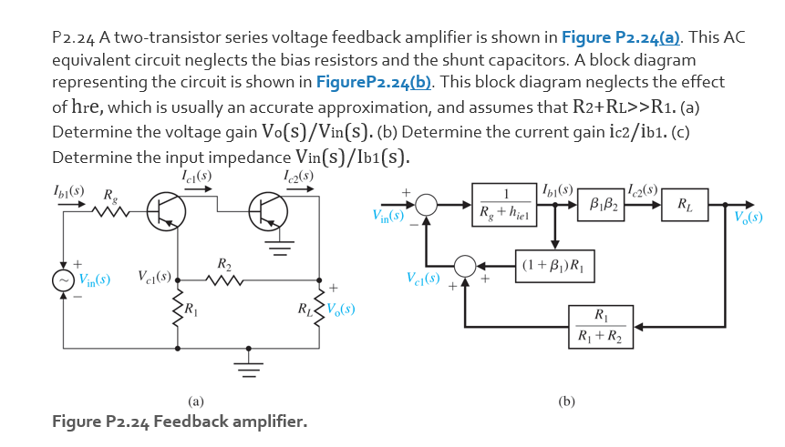
Transcribed Image Text:P2.24 A two-transistor series voltage feedback amplifier is shown in Figure P2.24(a). This AC
equivalent circuit neglects the bias resistors and the shunt capacitors. A block diagram
representing the circuit is shown in FigureP2.24(b). This block diagram neglects the effect
of hre, which is usually an accurate approximation, and assumes that R2+RL>>R1. (a)
Determine the voltage gain Vo(s)/Vin(s). (b) Determine the current gain ic2/ib1. (c)
Determine the input impedance Vin(s)/Ib1(s).
I(s) Rg
| 'b1(s)
l2(s)
Biß2
RL
Vin(s)
R+hjel
V(s)
8.
R2
(1+Bj)R|
Vin(8)
V1(s)
Vej(s)
+
RV(s)
R1
R¡ +R2
(a)
(b)
Figure P2.24 Feedback amplifier.
Expert Solution
This question has been solved!
Explore an expertly crafted, step-by-step solution for a thorough understanding of key concepts.

This is a popular solution!

Trending now
This is a popular solution!

Step by step
Solved in 4 steps with 4 images

Knowledge Booster


Learn more about
Need a deep-dive on the concept behind this application? Look no further. Learn more about this topic, electrical-engineering and related others by exploring similar questions and additional content below.Recommended textbooks for you
Power System Analysis and Design (MindTap Course …
Electrical Engineering
ISBN:
9781305632134
Author:
J. Duncan Glover, Thomas Overbye, Mulukutla S. Sarma
Publisher:
Cengage Learning
Power System Analysis and Design (MindTap Course …
Electrical Engineering
ISBN:
9781305632134
Author:
J. Duncan Glover, Thomas Overbye, Mulukutla S. Sarma
Publisher:
Cengage Learning