Q1 How is the initial current through a bulb affected by putting a capacitor in series in the circuit? Explain briefly.
Q1 How is the initial current through a bulb affected by putting a capacitor in series in the circuit? Explain briefly.

Introductory Circuit Analysis (13th Edition)
13th Edition
ISBN:9780133923605
Author:Robert L. Boylestad
Publisher:Robert L. Boylestad
Chapter1: Introduction
Section: Chapter Questions
Problem 1P: Visit your local library (at school or home) and describe the extent to which it provides literature...

Related questions

Question
Transcribed Image Text:A Matter-and-Interactions.pdf - Adobe Acrobat Reader DC (32-bit)
File Edit View Sign Window Help
Home
Tools
Matter-and-Interac. x
Sign In
794 (812 of 1030)
100%
a praic vutsIuc a cIcuiar capacnor IS apprUAmatry
Qy GIve a comprete vut orier expianation Tor uie venavior
of the current during the discharging of a capacitor in a
circuit consisting of a capacitor and light bulb. Include detailed
diagrams. Explain, don't just describe.
QIA GR
A more extensive analysis shows that this trend holds true for the
entire charging process: the capacitor with the narrower gap ends
up with more charge on its plates.
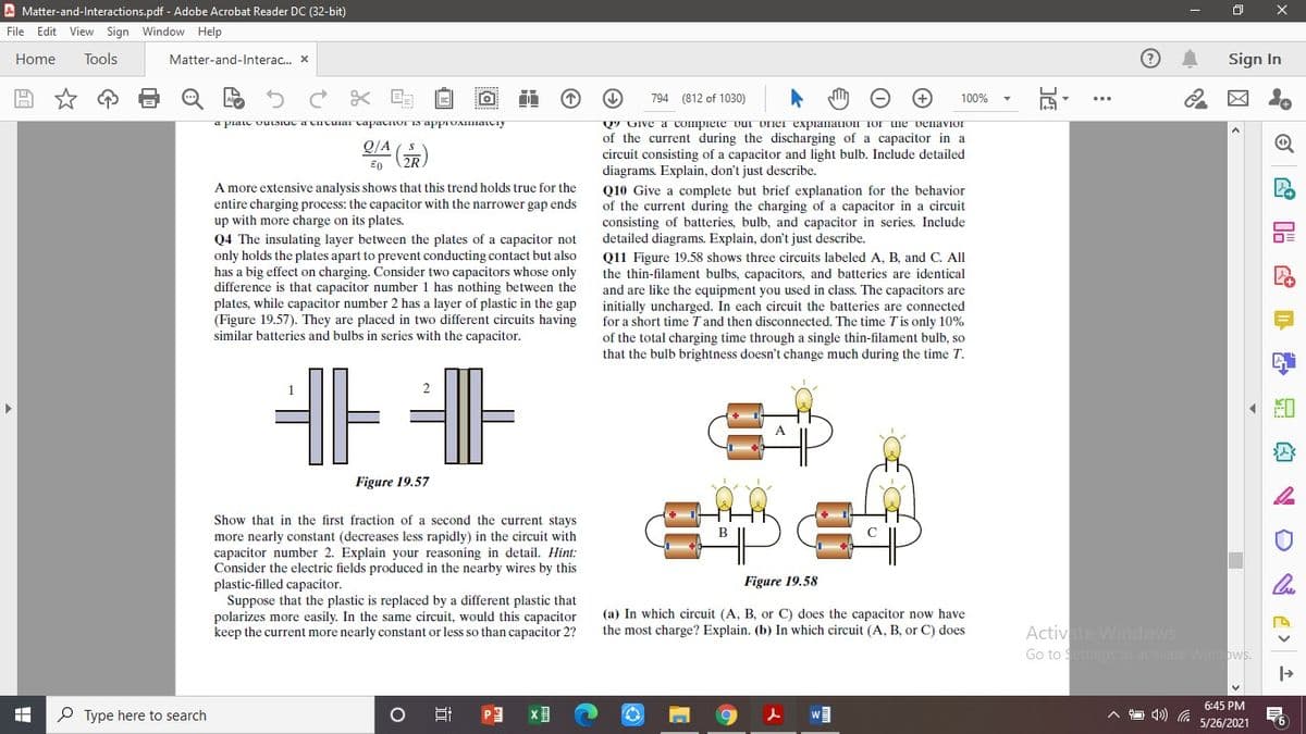
Q4 The insulating layer between the plates of a capacitor not
only holds the plates apart to prevent conducting contact but also
has a big effect on charging. Consider two capacitors whose only
difference is that capacitor number 1 has nothing between the
plates, while capacitor number 2 has a layer of plastic in the gap
(Figure 19.57). They are placed in two different circuits having
similar batteries and bulbs in series with the capacitor.
Q10 Give a complete but brief explanation for the behavior
of the current during the charging of a capacitor in a circuit
consisting of batteries, bulb, and capacitor in series. Include
detailed diagrams. Explain, don't just describe.
Q11 Figure 19.58 shows three circuits labeled A, B, and C. All
the thin-filament bulbs, capacitors, and batteries are identical
and are like the equipment you used in class. The capacitors are
initially uncharged. In each circuit the batteries are connected
for a short time Tand then disconnected. The time T'is only 10%
of the total charging time through a single thin-filament bulb, so
that the bulb brightness doesn't change much during the time T.
A
Figure 19.57
Show that in the first fraction of a second the current stays
more nearly constant (decreases less rapidly) in the circuit with
capacitor number 2. Explain your reasoning in detail. Hint:
Consider the electric fields produced in the nearby wires by this
plastic-filled capacitor.
Suppose that the plastic is replaced by a different plastic that
polarizes more easily. In the same circuit, would this capacitor
keep the current more nearly constant or less so than capacitor 2?
Figure 19.58
(a) In which circuit (A, B, or C) does the capacitor now have
the most charge? Explain. (b) In which circuit (A, B, or C) does
Activate Windows
Go to Settings to activate Windows.
6:45 PM
P Type here to search
PE
5/26/2021
近
Transcribed Image Text:A Matter-and-Interactions.pdf - Adobe Acrobat Reader DC (32-bit)
File Edit View Sign Window Help
Home
Tools
Matter-and-Interac. x
Sign In
794 (812 of 1030)
100%
QUESTI ONS
Q1 How is the initial current through a bulb affected by putting
a capacitor in series in the circuit? Explain briefly.
Q2 How is the charging time for a capacitor correlated with
the initial current? That is, if the initial current is bigger, is the
charging time longer, shorter, or the same? Explain briefly.
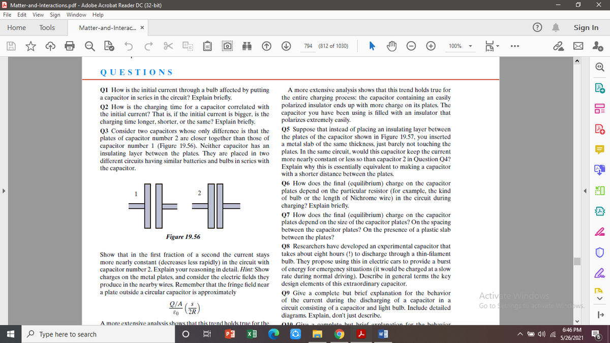
Q3 Consider two capacitors whose only difference is that the
plates of capacitor number 2 are closer together than those of
capacitor number 1 (Figure 19.56). Neither capacitor has an
insulating layer between the plates. They are placed in two
different circuits having similar batteries and bulbs in series with
the capacitor.
A more extensive analysis shows that this trend holds true for
the entire charging process: the capacitor containing an easily
polarized insulator ends up with more charge on its plates. The
capacitor you have been using is filled with an insulator that
polarizes extremely easily.
Q5 Suppose that instead of placing an insulating layer between
the plates of the capacitor shown in Figure 19.57, you inserted
a metal slab of the same thickness, just barely not touching the
plates. In the same circuit, would this capacitor keep the current
more nearly constant or less so than capacitor 2 in Question Q4?
Explain why this is essentially equivalent to making a capacitor
with a shorter distance between the plates.
Q6 How does the final (equilibrium) charge on the capacitor
plates depend on the particular resistor (for example, the kind
of bulb or the length of Nichrome wire) in the circuit during
charging? Explain briefly.
Q7 How does the final (equilibrium) charge on the capacitor
plates depend on the size of the capacitor plates? On the spacing
between the capacitor plates? On the presence of a plastic slab
between the plates?
Q8 Researchers have developed an experimental capacitor that
takes about eight hours (!) to discharge through a thin-filament
bulb. They propose using this in electric cars to provide a burst
of energy for emergency situations (it would be charged at a slow
rate during normal driving). Describe in general terms the key
design elements of this extraordinary capacitor.
1
Figure 19.56
Show that in the first fraction of a second the current stays
more nearly constant (decreases less rapidly) in the circuit with
capacitor number 2. Explain your reasoning in detail. Hint: Show
charges on the metal plates, and consider the electric fields they
produce in the nearby wires. Remember that the fringe field near
a plate outside a circular capacitor is approximately
Q9 Give a complete but brief explanation for the behavior
of the current during the discharging of a capacitor in a
circuit consisting of a capacitor and light bulb. Include detailed
diagrams. Explain, don't just describe.
O0 Civa complata hut briaf oxnlanati
Activate Windows
Go to Settings to activate Windows.
Q/A
A more extensive analvsis shows that this trend holds true for the
for the bahavior
6:46 PM
O Type here to search
w
5/26/2021
Expert Solution
This question has been solved!
Explore an expertly crafted, step-by-step solution for a thorough understanding of key concepts.

Step by step
Solved in 2 steps

Knowledge Booster


Learn more about
Need a deep-dive on the concept behind this application? Look no further. Learn more about this topic, electrical-engineering and related others by exploring similar questions and additional content below.Recommended textbooks for you
Introductory Circuit Analysis (13th Edition)
Electrical Engineering
ISBN:
9780133923605
Author:
Robert L. Boylestad
Publisher:
PEARSON

Delmar's Standard Textbook Of Electricity
Electrical Engineering
ISBN:
9781337900348
Author:
Stephen L. Herman
Publisher:
Cengage Learning

Programmable Logic Controllers
Electrical Engineering
ISBN:
9780073373843
Author:
Frank D. Petruzella
Publisher:
McGraw-Hill Education
Introductory Circuit Analysis (13th Edition)
Electrical Engineering
ISBN:
9780133923605
Author:
Robert L. Boylestad
Publisher:
PEARSON
Delmar's Standard Textbook Of Electricity
Electrical Engineering
ISBN:
9781337900348
Author:
Stephen L. Herman
Publisher:
Cengage Learning
Programmable Logic Controllers
Electrical Engineering
ISBN:
9780073373843
Author:
Frank D. Petruzella
Publisher:
McGraw-Hill Education

Fundamentals of Electric Circuits
Electrical Engineering
ISBN:
9780078028229
Author:
Charles K Alexander, Matthew Sadiku
Publisher:
McGraw-Hill Education

Electric Circuits. (11th Edition)
Electrical Engineering
ISBN:
9780134746968
Author:
James W. Nilsson, Susan Riedel
Publisher:
PEARSON

Engineering Electromagnetics
Electrical Engineering
ISBN:
9780078028151
Author:
Hayt, William H. (william Hart), Jr, BUCK, John A.
Publisher:
Mcgraw-hill Education,