Q1) If V1 (RMS) = 110 V (60 HZ) and transformer conversion ratio is 10: 1 according to the half-wave rectifier circuit below, find Vo (DC) value. (Diode is silicon Vd=0.7V)
Q1) If V1 (RMS) = 110 V (60 HZ) and transformer conversion ratio is 10: 1 according to the half-wave rectifier circuit below, find Vo (DC) value. (Diode is silicon Vd=0.7V)

Chapter15: Alternating-current Circuits
Section: Chapter Questions
Problem 59AP: Consider a power plant located 25 km outside a town delivering 50 MW of power to the town. The...

Related questions
Question
100%
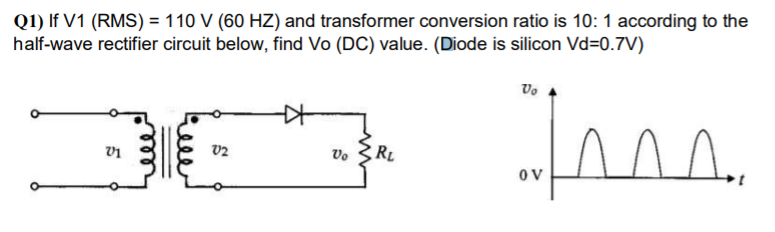
Transcribed Image Text:Q1) If V1 (RMS) = 110 V (60 HZ) and transformer conversion ratio is 10: 1 according to the
half-wave rectifier circuit below, find Vo (DC) value. (Diode is silicon Vd=0.7V)
RL
v2
Vo
OV
Expert Solution
This question has been solved!
Explore an expertly crafted, step-by-step solution for a thorough understanding of key concepts.

This is a popular solution!

Trending now
This is a popular solution!

Step by step
Solved in 2 steps with 1 images

Knowledge Booster


Learn more about
Need a deep-dive on the concept behind this application? Look no further. Learn more about this topic, physics and related others by exploring similar questions and additional content below.Recommended textbooks for you