Q1. a) Draw general diagrams for closed-loop control and open-loop control and describe their main differences. b) An RC network is given in Figure Q1.1 with the input voltage vin (t) and the output voltage v,(t). (i) Derive the transfer function of the network. (ii) If R1 = 10 k2, R2 = 1 MN, C = 20 µF, and 2 200 mathematically derive the system time response with an impulse input of magnitude 5. %3D ur, %3D %3D R1 Vin(t) C; R2 v.(t) Figure Q1.1. A RC network c) Simplify the block diagram shown in Figure Q1.2 and find out the system transfer function Y(s)/R(s). H2 R(s) G2 G3 Y(s) H1 Figure Q1.2. A block diagram
Q1. a) Draw general diagrams for closed-loop control and open-loop control and describe their main differences. b) An RC network is given in Figure Q1.1 with the input voltage vin (t) and the output voltage v,(t). (i) Derive the transfer function of the network. (ii) If R1 = 10 k2, R2 = 1 MN, C = 20 µF, and 2 200 mathematically derive the system time response with an impulse input of magnitude 5. %3D ur, %3D %3D R1 Vin(t) C; R2 v.(t) Figure Q1.1. A RC network c) Simplify the block diagram shown in Figure Q1.2 and find out the system transfer function Y(s)/R(s). H2 R(s) G2 G3 Y(s) H1 Figure Q1.2. A block diagram

Introductory Circuit Analysis (13th Edition)
13th Edition
ISBN:9780133923605
Author:Robert L. Boylestad
Publisher:Robert L. Boylestad
Chapter1: Introduction
Section: Chapter Questions
Problem 1P: Visit your local library (at school or home) and describe the extent to which it provides literature...

Related questions

Question
Transcribed Image Text:Q1. a)
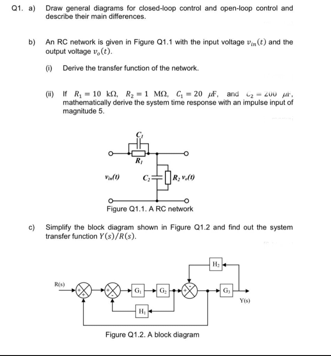
Draw general diagrams for closed-loop control and open-loop control and
describe their main differences.
b)
An RC network is given in Figure Q1.1 with the input voltage vin (t) and the
output voltage v,(t).
(i)
Derive the transfer function of the network.
(ii) If R, = 10 k2, R2 = 1 M2, C, = 20 uF, and C2 = 200 ur,
mathematically derive the system time response with an impulse input of
magnitude 5.
R1
Vin(1)
R2 vo(t)
Figure Q1.1. A RC network
c) Simplify the block diagram shown in Figure Q1.2 and find out the system
transfer function Y (s)/R(s).
H2
R(s)
G P G,
G3
Y(s)
H1
Figure Q1.2. A block diagram
Expert Solution
This question has been solved!
Explore an expertly crafted, step-by-step solution for a thorough understanding of key concepts.

Step by step
Solved in 5 steps with 16 images

Knowledge Booster


Learn more about
Need a deep-dive on the concept behind this application? Look no further. Learn more about this topic, electrical-engineering and related others by exploring similar questions and additional content below.Recommended textbooks for you
Introductory Circuit Analysis (13th Edition)
Electrical Engineering
ISBN:
9780133923605
Author:
Robert L. Boylestad
Publisher:
PEARSON

Delmar's Standard Textbook Of Electricity
Electrical Engineering
ISBN:
9781337900348
Author:
Stephen L. Herman
Publisher:
Cengage Learning

Programmable Logic Controllers
Electrical Engineering
ISBN:
9780073373843
Author:
Frank D. Petruzella
Publisher:
McGraw-Hill Education
Introductory Circuit Analysis (13th Edition)
Electrical Engineering
ISBN:
9780133923605
Author:
Robert L. Boylestad
Publisher:
PEARSON
Delmar's Standard Textbook Of Electricity
Electrical Engineering
ISBN:
9781337900348
Author:
Stephen L. Herman
Publisher:
Cengage Learning
Programmable Logic Controllers
Electrical Engineering
ISBN:
9780073373843
Author:
Frank D. Petruzella
Publisher:
McGraw-Hill Education

Fundamentals of Electric Circuits
Electrical Engineering
ISBN:
9780078028229
Author:
Charles K Alexander, Matthew Sadiku
Publisher:
McGraw-Hill Education

Electric Circuits. (11th Edition)
Electrical Engineering
ISBN:
9780134746968
Author:
James W. Nilsson, Susan Riedel
Publisher:
PEARSON

Engineering Electromagnetics
Electrical Engineering
ISBN:
9780078028151
Author:
Hayt, William H. (william Hart), Jr, BUCK, John A.
Publisher:
Mcgraw-hill Education,