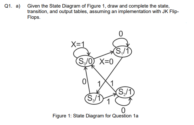
Q1. a) Given the State Diagram of Figure 1, draw and complete the state, transition, and output tables, assuming an implementation with JK Flip- Flops.


Q: G 12 H(s) = 2. 5+1 5 S+1 G₂(S) 6 543 S+3 Yı HIS) 42 Determine a multivariate integral controller for…
A:
Q: The open circuit test in a 100 kVA, 2000/200 V, 50 Hz, single phase transformer gives 200 V, 90 A, 5…
A:
Q: I₁ 120 V 1. Calculate the current I1, I2 and 13. 2. Calculate the total power dissipated in this…
A: Consider the the given circuit with the values of the resistance.
Q: A 500 turns coil has a self- inductance of 15 mH. What must be the current required to produced…
A: Current:It is the time rate of the change of the charges. It flows from high voltage to low voltage…
Q: A sine wave goes through 5 cycles in 10 µs What is its period? 15 μs 2 μs 50 μs 4 0.5 μs
A:
Q: e peak voltage
A: RMS voltage- Root mean square value is a amount of AC power drawn by resistor equivalent to DC power…
Q: Q2:- Two 50 MVA, 11kV synchronous generators are connected to common bus bar which supplies a…
A:
Q: Is a 16-bit register containing address of 64 KB segment with processor instructions. code segment…
A: Types of segment Code segment Stack segment Data segment... Etc
Q: What is the influence of transformer in single-phase connections transformers phase operation…
A: Types of primary and secondary coil connections Star Star Star delta Delta delta Delta star…
Q: How many wattmeters would be needed to measure the total three-phase power in a balanced three-phase…
A: In this questions, we need to tell about the how many wattmeter is required to measur the power in…
Q: write the way to find CMRR with all details and needed comprent Notes G₂ you have to draw the…
A: The Common - Mode Rejection Ratio is abbreviated as CMRR. The CMRR of an op-amp is used to identify…
Q: design a controlled single phase rectifier
A: Controlled single phase rectifier.
Q: Q1: Assume that V is a function of y and at y =2, V=5 volt and at y = 4, V = 10 volt. a) Find V, E,…
A: Given: Here we assume that V is the function of y.When y=2,V is varies as V=5 voltsand when…
Q: From the given circuit, take V₁ = 240, Z₁ = 20 - j3 ohms. Find the phase currents and line ZL…
A: In this question, A 3phase balance source supply to 3 phase balance load. We need to find the…
Q: match column a to b. Electricity flows from the power plant Through wires to the step-up…
A: 6 statements are given in column A which describe the complete power system from generation through…
Q: MAB orque in pound-feet. The inrush current to a synchronous motor is 235 amp when it is started…
A: Synchronous motor depend on interaction of magnetic field stator and rotor. stator contain the three…
Q: The full-scale deflecting torque of a 20 A moving-iron ammeter is 6 x 10⁻⁵ N-m. What is the rate of…
A: Given a moving iron ammeter having, Deflecting torque, τd=6×10⁻⁵ N.m Current, I = 20 A Rate of…
Q: Mass of an electron?
A: The solution is provided in the following section.
Q: What is the minimum sum-of-products expression for the following Kmap?
A:
Q: Determine β (DC) for a transistor where Ib = 75 μA and Ic = 4 mA
A:
Q: The shaft torque of a diesel motor driving a 100V dc shunt-wound generator is 25Nm. The armature…
A:
Q: Is a 16-bit register containing address of 64 KB segment with processor instructions. code segment a…
A: Stack segment is also a 16 bit register contatin 64 KB segment with programs stack Code segment is…
Q: 3. A 2/30⁰-MV voltage source is in series with the parallel arrangement of an inductor and a…
A: In the questions, we need to change the circuit into its equivalent current source.
Q: design a uncontrolled three phase rectifier
A: Uncontrolled three-phase rectifier: Rectifier is used to convert the AC signal into DC signal. When…
Q: Q2. Calculate the lowest three (n=1,2,3) blind speeds of an MTI radar operating at 3 GHz, with a PRF…
A: To convert a unit of Meter per second into Kilometer per hour, 1 m/s = 3.6 km/h To convert a unit…
Q: duce the block diagram and obtain its closed-loop transfer function R(s) G₁ H₂ G₂ G3 G4 H₂ C(s)
A:
Q: G=1/R is called [Select] Y = 1/Z where Z is a complex impedance. Y is called [Select] [Select]…
A: Given, G=1R is called _____ and has units of Siemens (S). Y=1Z where Z is a complex impedance. Y is…
Q: Example 7.33. Two coils of inductances 4 and 6 henry are connected in parallel. If their mutual…
A: Given: Two coil of inductances 4 and 6 henry are connected in parallel, L1=4 H L2=6 H Mutual…
Q: For each of the following transfer functions, write, by inspection, the general form of the step…
A: Transfer function is also known as a network function . In a transfer function theoretical model…
Q: A 8-stage impulse voltage generator is connected to a test object of load capacitance of 5000pF with…
A: Give information about an impulse voltage generator is, Number of stages N=8. Wave tail time…
Q: Q2/A Shunt motor having a field resistance of 50 and an armature resistance of 0.5 is connected to a…
A:
Q: TOPIC: AMPLITUDE MODULATION AND DEMODULATION Please answer this 2 question thanks. 1. What is…
A: We are authorized to answer one question at a time, since you have not mentioned which question you…
Q: What is the purpose of polarity testing in order to properly perform paralleling of transformers?
A: Polarity test define the direction of the current. it helps the interconnecting the primary and…
Q: Topic: Amplitude Modulation and Demodulation: please answer this question thanks. 1. What are the…
A: Brief description: Envelope detector is a demodulator circuit which is used to demodulate amplitude…
Q: What will happen if proper polarity is taken for granted in paralleling transformer? If voltages are…
A: The polarity of the transformer means the instantaneous direction of the second induced emf. If the…
Q: (b) Find V across the load in the AC circuit given in Figure 4.1 (assume that both AC sources have…
A: As per company guidelines we are supposed to answer only one question. Kindly repost other questions…
Q: Find the total energy stored in the circuit of Figure below 60 L₁ = 2mH 302 = 4 mH m www C₁ = 20 µF…
A:
Q: For the 3-phase, 3 wire system below. Compute for the line currents, total real power, total…
A: The 3-phase device is a cost-effective way of bulk power transmission over lengthy distances and for…
Q: Determine α (DC) for a transistor where Ib = 75 μA and Ic = 4 mADetermine α (DC) for a transistor…
A:
Q: QI Calculate ict) in the circuit of Figure below 652 X SA SH +=o tart
A:
Q: Example 4.6: A varactor has a maximum capacitance of 80 pF and is used in a tuned circuit with a 100…
A:
Q: Explain the working of fluorescent tube with the help of circuit diagram giving the function of…
A: Fluorescent Tube It is gas-discharge mercury-vapor low-pressure lamp that utilizes fluorescence to…
Q: Q1// Find I1, I2 & 13? Where Ri= 1022, R₂-40N & R3-2092 Vi=10v & v₂=20v R₁ V₁ R₂ R3 + V₂
A: In this question, We need to determine the current in the resistances R1, R2 and R3. We know…
Q: 1. The synchronous motor is not inherently self-st 2. As the load is applied to a synchronous motor,…
A: Synchronous motor is a motor that runs at a constant speed. the rotor and stator are in synchronism.
Q: Determine Vce in the given circuit if VBB = 10V, VCC = 15V, RB = 10kS2 and RC = 110 S. Assume ß =…
A:
Q: In what ways are integrated circuits better than discrete ones.
A: Integrated circuits: A semiconductor wafer on which hundreds or millions of small diodes, resistors,…
Q: 5. Find the input impedance at 20 krad/s for the circuit shown in Figure 4. 3 mH 200 £2 m vooo 0.592…
A: Since you have posted the multiple questions so we are supposed to answer the 1st one. 5) In this…
Q: A resistor of unknown resistance is in parallel with a 12-2 resistor. A battery of emf 24 V and…
A: circuit is solve as by solve simple parallel connection
Q: E7.17 The switch in the network in Fig. E7.17 moves from position 1 to position 2 at = 0. ANSWER:…
A:
Q: Q2// Find the current at 10 22 by using thevenin's theorem? 292 122 10v= 592 VIL 1092 +1+ 20v
A:

Step by step
Solved in 2 steps with 2 images


- Q5 A Moore machine is to detect three or more consecutive zeros on an input bitstream using D flip flops. (a) Present the truth table and state diagram. (b) Interpret the simplified logic expression using K-Map. (c) Sketch the circuit with appropriate labeling.question 3c Draw a block diagram of the system to be designed, showing the interconnection between the Next State Decoder and the J-K flip-flopsDesign a circuit which would follow assigned number 35746 by using one JK, one D, one Flip-flop. THere is no input it just repeats the cycle. For the circuit you obtained, draw state diagram by considering all used and unused states.
- b) Figure 2.1 shows the input and the corresponding outputs of a flip-flop whereby QM and Q are taken from the Master latch and the Slave latch respectively. Give the full name of the flip-flop being used here and justify your answers. Use a block diagram for each latch, provide a circuit diagram of the flip-flop you have named.For the circuit below X=1,B=1,Y=1,C=1. What will be the next state for the flip-flop?A. set B. reset C. complement D. No change E. noneExplain the difference between D-Latch and D flip flop with the help of diagram? If the ̅s and ̅R waveforms in Figure 2 are applied to the inputs of the latch as shown, determine the waveform that will be observed on the Q output. Assume that Q is initially LOW Kindly Handwritten
- Design of a digital electronic circuit that produces 4 bits of binary numbers sequentially and repeatedly to move the Stepper Motor in Full Step mode such as : 0011 1001 1100 0110 0011. To generate predefined binary data, You can use a flip-flop that is assembled into a Sync Counter. To stringing a flip-flop into a Sync Counter must be known Excitation Table or Table Transition from flip-flop. Citation Table determined by Table The Truth of the Flip-Flop. Design of Synchronous Counter circuit to generate 4 bits of Motor drive data Stepper on Full Step mode using a D flip-flop?F4 Using two flip-flops and basic gates, construct the circuit of the given state diagram below. Provide the following: State Table, Flip-flop equations, Circuit Diagram. Follow correct label names: Q0, Q1 – prev/present states D0, D1 – D-FF names X – input Y - outputFor the path in the following figure, determine which latches borrow time and if any setup time violations occur. Do this for a cycle time of 1000 ps and a duty cycle of 50%. Assume for the latches and flip-flops the setup and delay time is 100 ps. Use Δ1 = 250 ps , Δ2 = 600 ps, Δ3 = 600 ps. Will the circuit function correctly with the given combinational circuit delays? Explain.
- The signals below, CK and D are the clock and D inputs to two different components: a D latch and a D flip-flop. Complete the timing diagram below for the outputs from a D latch and D flip-flop, Qlatch and Qff, respectively. (Digital Circuit) ...You are asked to design a synchronous counter that will count the sequence 1 > 2>3>1. (a) Represent these decimal numbers in 2 bits binary numbers. (b) Write down the state table. (c) Find the functions for the next state of the state table using K-map. (d) Draw the circuit (You need to consider D flip-flops as memory unit).Which of the following is/are true about RS flip-flop? a. It outputs Logic 1 b. It outputs Logic 0 c. It copies the previous Q d. a & b e. a, b & c f. None of theabove