Q2 (a) Outline with the aid of a suitable diagram the necessary power conversion stages required to interface a small permanent magnet (PM) wind generator to a 3 phase AC grid. (b) Given the operating conditions for a stand alone star connected 3 phase synchronous generator outlined in Table Q2b construct a scaled phasor diagram and determine the resultant load current and power factor. On the same phasor diagram indicate the resultant changes when the load current increases by approximately 20% for no change in (lagging) power factor or excitation voltage. Value 415V Parameter Excitation Voltage Load Angle Xs 300V 20° 1.50 Table Q2b A star connected 3 phase wound field synchronous generator with a (c) synchronous reactance of 122 is connected to a 11kV (line) grid and supplies 1MW at 0.92 lagging power factor at its terminals. Calculate the phase current and resultant voltage across the synchronous reactance (Vxs), and from a scaled phasor diagram graphically determine the required excitation voltage (Eph) and load angle (8).
Q2 (a) Outline with the aid of a suitable diagram the necessary power conversion stages required to interface a small permanent magnet (PM) wind generator to a 3 phase AC grid. (b) Given the operating conditions for a stand alone star connected 3 phase synchronous generator outlined in Table Q2b construct a scaled phasor diagram and determine the resultant load current and power factor. On the same phasor diagram indicate the resultant changes when the load current increases by approximately 20% for no change in (lagging) power factor or excitation voltage. Value 415V Parameter Excitation Voltage Load Angle Xs 300V 20° 1.50 Table Q2b A star connected 3 phase wound field synchronous generator with a (c) synchronous reactance of 122 is connected to a 11kV (line) grid and supplies 1MW at 0.92 lagging power factor at its terminals. Calculate the phase current and resultant voltage across the synchronous reactance (Vxs), and from a scaled phasor diagram graphically determine the required excitation voltage (Eph) and load angle (8).

Power System Analysis and Design (MindTap Course List)
6th Edition
ISBN:9781305632134
Author:J. Duncan Glover, Thomas Overbye, Mulukutla S. Sarma
Publisher:J. Duncan Glover, Thomas Overbye, Mulukutla S. Sarma
Chapter3: Power Transformers
Section: Chapter Questions
Problem 3.38P: Consider a three-phase generator rated 300MVA,23kV, supplying a system load of 240 MA and 0.9 power...

Related questions

Question
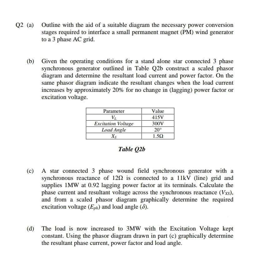
Transcribed Image Text:Q2 (a) Outline with the aid of a suitable diagram the necessary power conversion
stages required to interface a small permanent magnet (PM) wind generator
to a 3 phase AC grid.
(b) Given the operating conditions for a stand alone star connected 3 phase
synchronous generator outlined in Table Q2b construct a scaled phasor
diagram and determine the resultant load current and power factor. On the
same phasor diagram indicate the resultant changes when the load current
increases by approximately 20% for no change in (lagging) power factor or
excitation voltage.
Value
Parameter
V.
415V
Excitation Voltage
Load Angle
300V
20°
Xs
1.50
Table Q2b
A star connected 3 phase wound field synchronous generator with a
synchronous reactance of 120 is connected to a 11kV (line) grid and
supplies 1MW at 0.92 lagging power factor at its terminals. Calculate the
phase current and resultant voltage across the synchronous reactance (Vxs),
and from a scaled phasor diagram graphically determine the required
excitation voltage (Eph) and load angle (8).
(c)
(d) The load is now increased to 3MW with the Excitation Voltage kept
constant. Using the phasor diagram drawn in part (c) graphically determine
the resultant phase current, power factor and load angle.
Expert Solution
This question has been solved!
Explore an expertly crafted, step-by-step solution for a thorough understanding of key concepts.

This is a popular solution!

Trending now
This is a popular solution!

Step by step
Solved in 2 steps with 2 images

Knowledge Booster


Learn more about
Need a deep-dive on the concept behind this application? Look no further. Learn more about this topic, electrical-engineering and related others by exploring similar questions and additional content below.Recommended textbooks for you
Power System Analysis and Design (MindTap Course …
Electrical Engineering
ISBN:
9781305632134
Author:
J. Duncan Glover, Thomas Overbye, Mulukutla S. Sarma
Publisher:
Cengage Learning
Power System Analysis and Design (MindTap Course …
Electrical Engineering
ISBN:
9781305632134
Author:
J. Duncan Glover, Thomas Overbye, Mulukutla S. Sarma
Publisher:
Cengage Learning