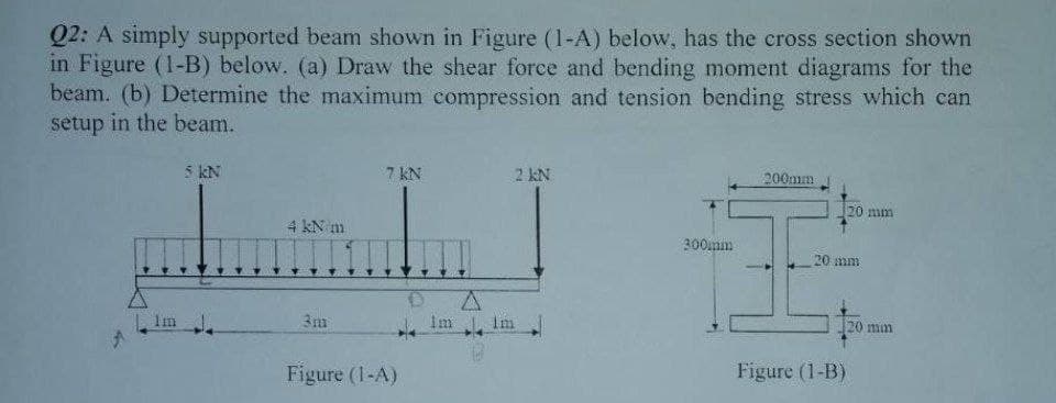
Q2: A simply supported beam shown in Figure (1-A) below, has the cross section shown in Figure (1-B) below. (a) Draw the shear force and bending moment diagrams for the beam. (b) Determine the maximum compression and tension bending stress which can setup in the beam. 7 kN 4 kN/m IZLI 3m 5 kN Figure (1-A) 2 kN A Im Im 300mm 200mm 20 mm 20 mm Figure (1-B) 20 mm
Q2: A simply supported beam shown in Figure (1-A) below, has the cross section shown in Figure (1-B) below. (a) Draw the shear force and bending moment diagrams for the beam. (b) Determine the maximum compression and tension bending stress which can setup in the beam. 7 kN 4 kN/m IZLI 3m 5 kN Figure (1-A) 2 kN A Im Im 300mm 200mm 20 mm 20 mm Figure (1-B) 20 mm

Mechanics of Materials (MindTap Course List)
9th Edition
ISBN:9781337093347
Author:Barry J. Goodno, James M. Gere
Publisher:Barry J. Goodno, James M. Gere
Chapter4: Shear Forces And Bending Moments
Section: Chapter Questions
Problem 4.5.21P: The beam ABC shown in the figure is simply supported at A and B and has an overhang from B to C Draw...

Related questions
Question
Transcribed Image Text:Q2: A simply supported beam shown in Figure (1-A) below, has the cross section shown
in Figure (1-B) below. (a) Draw the shear force and bending moment diagrams for the
beam. (b) Determine the maximum compression and tension bending stress which can
setup in the beam.
Im
5 kN
4 kN m
3m
7 KN
Figure (1-A)
Im
A
2 kN
Im
300mm
200mm
20 mm
20 mm
Figure (1-B)
20 min
Expert Solution
This question has been solved!
Explore an expertly crafted, step-by-step solution for a thorough understanding of key concepts.

Step by step
Solved in 5 steps with 2 images

Knowledge Booster


Learn more about
Need a deep-dive on the concept behind this application? Look no further. Learn more about this topic, mechanical-engineering and related others by exploring similar questions and additional content below.Recommended textbooks for you
Mechanics of Materials (MindTap Course List)
Mechanical Engineering
ISBN:
9781337093347
Author:
Barry J. Goodno, James M. Gere
Publisher:
Cengage Learning
Mechanics of Materials (MindTap Course List)
Mechanical Engineering
ISBN:
9781337093347
Author:
Barry J. Goodno, James M. Gere
Publisher:
Cengage Learning