Q2: The rigid beam shown in fig2 is held by two vertical rods at A and C. If a 60 KN load is applied at B what is the displacement of this point (B). Aluminum L- 3 m A- 500 mm E= 70 GPa Steel L- 4 m A- 300 mm E= 200 GPa Fig 2 3.5 m 2.5 m
Q2: The rigid beam shown in fig2 is held by two vertical rods at A and C. If a 60 KN load is applied at B what is the displacement of this point (B). Aluminum L- 3 m A- 500 mm E= 70 GPa Steel L- 4 m A- 300 mm E= 200 GPa Fig 2 3.5 m 2.5 m

Mechanics of Materials (MindTap Course List)
9th Edition
ISBN:9781337093347
Author:Barry J. Goodno, James M. Gere
Publisher:Barry J. Goodno, James M. Gere
Chapter2: Axially Loaded Members
Section: Chapter Questions
Problem 2.3.21P: A slightly tapered bar AB of solid circular crass section and length L is supported at end B and...

Related questions

Question
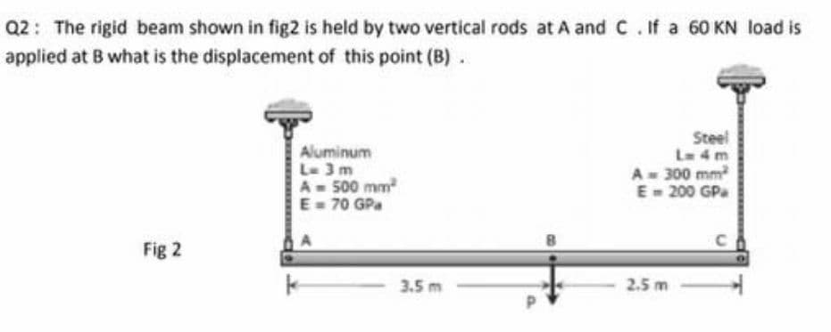
Transcribed Image Text:Q2: The rigid beam shown in fig2 is held by two vertical rods at A and C. If a 60 KN load is
applied at B what is the displacement of this point (B) .
Aluminum
L- 3 m
A-500 mm
E= 70 GPa
Steel
Le 4 m
A- 300 mm
E- 200 GP
Fig 2
3.5 m
2.5 m
Expert Solution
This question has been solved!
Explore an expertly crafted, step-by-step solution for a thorough understanding of key concepts.

Step by step
Solved in 2 steps with 2 images

Knowledge Booster


Learn more about
Need a deep-dive on the concept behind this application? Look no further. Learn more about this topic, mechanical-engineering and related others by exploring similar questions and additional content below.Recommended textbooks for you
Mechanics of Materials (MindTap Course List)
Mechanical Engineering
ISBN:
9781337093347
Author:
Barry J. Goodno, James M. Gere
Publisher:
Cengage Learning
Mechanics of Materials (MindTap Course List)
Mechanical Engineering
ISBN:
9781337093347
Author:
Barry J. Goodno, James M. Gere
Publisher:
Cengage Learning