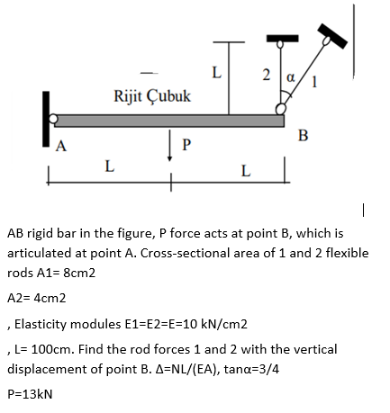
AB rigid bar in the figure, P force acts at point B, which is articulated at point A. Cross-sectional area of 1 and 2 flexible rods A1= 8cm2 A2= 4cm2 ,Elasticity modules E1=E2=E=10 kN/cm2 L= 100cm. Find the rod forces 1 and 2 with the vertical


Q: The AB rigid beam in the figure rests on AC and BD supports. The length of the AC support is LAC =…
A: Part 1) The equivalent load for a uniformly varying load w kNm acting over a beam span of L m is…
Q: Q2: A bar of steel, having a rectangular cross-section of 7.5 cm by 2.5 cm (see figure below),…
A:
Q: image479
A: Draw the FBD diagram of the given system:
Q: A circular tube of inner radius r1 and outer radius r2 is subjected to a torque produced by forces P…
A: a-calculate the r2 the minimum permissible outer radius of the tube given…
Q: 2. As shown in the figure, a rigid beam with negligible mass is pinned at one end and supported by…
A:
Q: Q-4 The polymer bar shown in Figure Q-4 has a width b = 50 mm, a depth d= 100 mm, and a height h=…
A:
Q: Q.3 A steel column (E = 30 x10 3 ksi) that is fixed at the base and free at the top is constructed…
A:
Q: A bracket ABCD having a hollow circularcross section consists of a vertical arm AB (L 5 6 ft),a…
A:
Q: 30. A bar of circular cross section is clamped at ends P and Q as shown in the figure. A torsional…
A: Consider the torque at end P is T1 and the torque at the end Q is T2.
Q: Determine the maximum tensile stress σt , maximum compressive stress σc, and maximum shear stress…
A:
Q: An eccentrically loaded foundation is shown in Figure P4.8. Use FS of 4 and determine the maximum…
A: According to the given information, we have γ=17kN/m3c'=0ϕ'=36°by…
Q: The BC rod, which is assumed to be rigid and massless in Figure, stands horizontally with the help…
A: Draw the deflection diagram. From the deflection diagram, the relation between deflections is,
Q: H.W.1: A steel bar 6 m long is 5 cm in diameter for 3m of its length and 2.5 cm in diameter for the…
A:
Q: A prismatic bar AB with a solid circularcross section (diameter d) is loaded by a distributedtorque…
A:
Q: As shown in the figure, a curved bar ABC is subjected to loads in the form of two equal and opposite…
A: Given Data: Force P=5.1 KN Diameter d=2 m Angle θ=36°
Q: In the figure, one end of a uniform beam of weight 440 N is hinged to a wall; the other end is…
A: Consider the FBD as shown below.
Q: In the figure, aluminum [E = 60 GPa] links (1) and (2) support rigid beam ABC. Link (1) has a…
A: Data given - a = 1380 mm, b = 760 mm, L₁= 2570 mm, and L₂ = 4650 mm. P = 32 kN A2 = 430 mm2 A1 =…
Q: The beam in the figure below is perpendicular to the wall and supported at the wall by a hinge at…
A:
Q: In the figure, one end of a uniform beam of weight 410 N is hinged to a wall; the other end is…
A: ...
Q: 2.3-3 A steel bar AD (see figure) has a cross-sectional area of 0.40 in.² and is loaded by forces P,…
A:
Q: Q2: One side of a petrol drill pipe, as shown in the figure, has been lifted with the use of a crane…
A: The cross-sectional diagram of the pipe is shown below.
Q: A solid circular steel cylinder S is encased in a hollow circular copper tube C (see figure). The…
A: Given, Compressive force P= 97 kN The cross-section area of the steel cylinder, As=1422 mm2 Modulus…
Q: The pin-jointed frame work in the figure below has D F members of cross sectional area A=1200mm2 and…
A: By inspection it is clear that truss has only two zero force members and they are member DE and EF.
Q: The cantilever truss in the figure is hinged at D and E. Find the force in member CE. 1000 Ib 60 60°…
A:
Q: A plane frame with pin supports at A and Ehas a cable attached at C, which runs over a…
A: a.Free body diagram: No horizontal force on frame,henceEx=0Now,Ey+Ay=500lb⇒Ey=500lb-AyNow,Net…
Q: A column ABC is supported at ends A and C and compressed by an axial load P (figure (a)). Lateral…
A: Given data: Modulus of elasticity , E = 29100 ksi Proportional limit = 50ksi Total height of the…
Q: A circular bar, with shear modulus 40 GPa and radius 10 mm, is subjected to torques at points A, B,…
A:
Q: A cantilevered bar in the figure is acted up on by a system of forces Fx =75 lb, Fy 200 lb, and Fz =…
A: according to the given details
Q: A homogeneous 1.5 kN bar AB carries a 2 kN force as shown in the figure. The bar is supported by a…
A:
Q: The stair beam in the figure will have support reactions. A support is a fixed, B support is a…
A:
Q: In the figure, one end of a uniform beam of weight 130 N is hinged to a wall; the other end is…
A:
Q: The cantilever truss in the figure is hinged at D and E. Find the force in member AC. 1000 1b 600…
A:
Q: The cantilever truss in the figure is hinged at D and E. Find the force in member BC. 1000 1b 60 60°…
A:
Q: The assembly shown in the figure consists of a brass core (diameter d1 = 0.25 in.) surrounded by a…
A:
Q: P1 B. P2 A -ak b
A:
Q: The cantilever truss in the figure is hinged at D and E. Find the force in member AB. 1000 Ib 60 60…
A:
Q: In the figure, one end of a uniform beam of weight 130 N is hinged to a wall; the other end is…
A: To find: The tension in the wire. Given: The weight of the one end of the beam is hinged to the wall…
Q: The cantilever truss in the figure is hinged at D and E. Find the force in member BD. 1000 1b 60°…
A: As per given question We have to determine all forces members including BD
Q: In the figure, copper AB copper with a diameter of 24 mm and BC steel bars with a diameter of 20 mm…
A:
Q: *2.5-11 A rigid triangular frame is pivoted at C and held by two identical horizontal wires at…
A:
Q: A 20.0-kg floodlight in a park is supported at the end of a horizontal beam of negligible mass that…
A: Given:- The free body diagram for the given problem is:
Q: support reaction forces
A: Given: A plane frame with load 2P as shown in Fig To determine all support reaction Forces
Q: 1,2 m -0,6 m Im Çap:50 mm The system in the figure is carried by a 50 mm diameter column. If the…
A: Solution: We need to find the critical load to prevent the column BC from buckling, since both ends…
Q: -20kN 8. A steel bar ABCD 4 m long is subjected to force as shown in figure below. Find the…
A: Answer: The total elongation of the bar is 1.7507 mm.
Q: Consider the circular bent rod with diameter 20 mm. The free-end of the bend is subjected to loads…
A:
Q: In the figure, aluminum [E = 75 GPa] links (1) and (2) support rigid beam ABC. Link (1) has a…
A: Consider a bar having cross-sectional area A,Length L and Young's Modulus E is subjected to axial…
Q: A flat bar of rectangular cross section, length L, and constant thickness tis subjected to tension…
A:
Q: Q2: A bar of steel, having a rectangular cross-section of 7.5 cm by 2.5 cm (see figure below),…
A: Given data: Width of bar, w = 7.5 cm. Height of the bar, h = 2.5 cm. Length of the bar, L = 100 cm.…
Q: A beam weighing 50 kg is attached to a pin at C and supported by a steel cable OA with Young's…
A: 1) Free body diagram of the given beam is drawn below 2) To find Tension in the steel cable OA we…
5

Step by step
Solved in 2 steps with 1 images


- Bar ABC is fixed at both ends (see figure) and has load P applied at B. Find reactions at A and C and displacement SBif P = 200 kN. L = 2 m, t = 20 mm, b, = 100 mm, b2= 115 mm, and E = 96 GPa.Space frame A BCD is clamped at A, except it is Free to translate in the .v direction. There is also a roller support at D, which is normal to line CDE. A triangularly distributed Force with peak intensity q0 = 75 N/m acts along AB in the positive - direction. Forces Px= 60 N and Pz = = 45 N are applied at joint C, and a concentrated moment My = 120 N . m acts at the mid-span of member BC. (a) Find reactions at supports A and I). (b) Find internal stress resultants N. E’I T, and .11 at the mid-height of segment AB.A rigid bar AB having a mass M = 1.0 kg and length L = 0.5 m is hinged at end A and supported at end B by a nylon cord BC (see figure). The record has cross-sectional area A = 30 mm2. length b = 0.25 m. and modulus of elasticity E = 2.1 GPa. If the bar is raised to its maximum height and then released, what is the maximum stress in the cord?
- A hollow circular pipe (see figure} support s a load P that is uniformly distributed around a cap plate at the top of the lower pipe. The inner and outer diameters of the upper and lower parts of the pipe are d1= 50 mm, d2= 60 mm, rf3 = 57 mm, and d1= 64 mm, respectively. Pipe lengths are Lt= 2 m and L, = 3 m. Neglect the self-weight of the pipes. Assume that cap plate thickness is small compared to I, and E,. Let E = 110 MPa. (a) If the tensile stress in the upper part is d = 10.5 MPa. what is load PI Also, what are reactions ft, at the upper support and R-, at the lower support? What is the stress ar(MPa) in the lower part? (b) Find displacement S(mm) at the cap plate. Plot the axial force diagram (AFD) [Ar(.f)] and axial displacement diagram (ADD)[5(.t)]. (c) Add the uniformly distributed load q along the censorial axis of pipe segment 2. Find q (kN/m) so that It, = 0. Assume that load P from part (a) is also applied.A space truss is restrained at joints O, A. B. and C, as shown in the figure. Load P is applied at joint A and load IP acts downward at joint C. (a) Find reaction force components Ax, By, and B. in terms of load variable P. (b) Find the axial force in truss member AB in terms of load variable P.A uniform bar AB of weight W = 25 N is supported by two springs, as shown in the figure. The spring on the left has a stiffness k[= 300 N/m and natural length Lt=250 mm. The corresponding quantities for the spring on the right are k2= 400 N/m and L^ = 200 mm. The distance between the springs is L = 350 mm, and the spring on the right is suspended from a support that is a distance it = SO mm below the point of support for the spring on the left. Neglect the weight of the springs. (a) At what distance x from the left-hand spring (figure part a) should a load P = 18 N be placed in order to bring the bar to a horizontal position? (b) If P is now removed, what new value of k{is required so that the bar (figure part a) will hang in a horizontal position underweight If? (c) If P is removed and kt= 300 N/m. what distance b should spring ktbe moved to the right so that the bar (figure part a) will hang in a horizontal position under weight II"? (d) If the spring on the left is now replaced by two springs in series (kt= 300 N/m, kt) with overall natural length Lt= 250 mm (see figure part b). what value of k; is required so that the bar will hang in a horizontal position under weight IF?
- -21 Plastic bar AB of rectangular cross section (6 = 0.75 in. and h = 1.5 in.) and length L = 2 Ft is Fixed at A and has a spring support (Ar = 18 kips/in.) at C (see figure). Initially, the bar and spring have no stress. When the temperature of the bar is raised hy foot. the compressive stress on an inclined plane pq at Lq = 1.5 Ft becomes 950 psi. Assume the spring is massless and is unaffected by the temperature change. Let a = 55 × l0-6p and E = 400 ksi. (a) What is the shear stresst9 on plane pq? What is angle 07 =1 Draw a stress element oriented to plane pq, and show the stresses acting on all laces of this element. (c) If the allowable normal stress is ± 1000 psi and the allowable shear stress is ±560 psi, what is the maximum permissible value of spring constant k if the allowable stress values in the bar are not to be exceeded? (d) What is the maximum permissible length L of the bar if the allowable stress values in the bar are not be exceeded? (Assume £ = IB kips/in.) (e) What is the maximum permissible temperature increase (A7") in the bar if the allowable stress values in the bar are not to be exceeded? (Assume L = 2 ft and k = L& kips/inThe horizon Lai rigid beam A BCD is supported by vertical bars BE and CF and is loaded by vertical Forces P, = 400 KN arid P2= 360 kN acting at points A and D, respectively (see figure). Bars BE and CF are made of steel (£ = 200 GPa} and have cross-sectional areas Ag=11,100 mm" and ABE= 9280 mm-. The distances between various points on the bars are shown in the figure. Determine the vertical displacements SAand SDof points A and D, respectively.A plane frame is restrained al joints A and C, as shown in the figure. Members AB and BC are pin connected at B. A triangularly distributed lateral load with a peak intensity or 90 lb/ft acts on AB. A concentrated moment is applied at joint C. (a) Find reactions at supports A and C. (b) Find internal stress resultants A', V, and \f at x = 3 ft on column AB.
- An aluminum bar AD (see figure) has a cross-sectional area of 0.40 in- and is loaded by Forces Pi= 1700 lb, Pz- 1200 lb, and P3 = 1300 lb. The lengths of the segments of the bar are ti = 60 in., b = 24 in.T and c = 36 in. (a) Assuming that the modulus of elasticity is E = 10.4 × 10o psi. calculate the change in length of the bar. Does the bar elongate or shorten? (b) By what amount ^should the load Pibe increased so that the bar does not change in length when the three loads are applied? (c) IF Pzremains at 1300 lb, what revised cross-sectional area For segment AB will result in no change of length when all three loads are applied?Two pipe columns (AB, FC) are pin-connected to a rigid beam (BCD), as shown in the figure. Each pipe column has a modulus of E, but heights (L1or L2) and outer diameters (d1or different for each column. Assume the inner diameter of each column is 3/4 of outer diameter. Uniformly distributed downward load q = 2PIL is applied over a distance of 3L/4 along BC, and concentrated load PIA is applied downward at D. (a) Derive a formula for the displacementA vertical pole of solid, circular cross section is twisted by horizontal forces P = 5kN acting at the ends of a rigid horizontal arm AB (see figure part a). The distance from the outside of the pole to the line of action of each force is c = 125 mm (sec figure part b) and the pole height L = 350 mm. (a) If the allowable shear stress in the pole is 30 MPa, what is the minimum required diameter dminof the pole? (b) What is the torsional stiffness of the pole (kN · m/rad)? Assume that G = 28 GPa. (c) If two translation al springs, each with stiffness k =2550 kN/m, are added at 2c/5 from A and B (see figure part c), repeat part (a) to find dmin. Hint: Consider the pole and pair of springs as "springs in parallel."