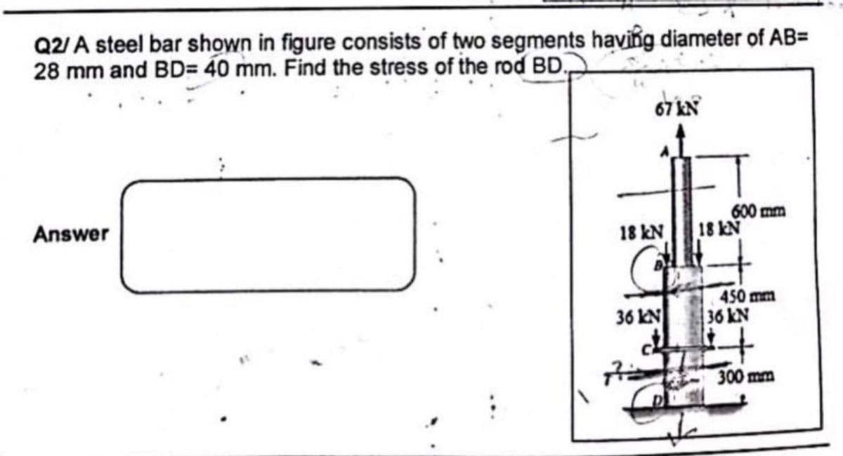
Q2/ A steel bar shown in figure consists of two segments having diameter of AB= 28 mm and BD= 40 mm. Find the stress of the rod BD.
Q: Q1/A steel bar ABCD (4m) long is subjected to forces as shown in Figure. Find the stresses in each…
A:
Q: The bracket as shown in Figure Q4 is subjected to forces 750 N, 300 N and moment 500 Nm. The bracket…
A:
Q: "Prob. 3.3-10. A 12-ft beam AB that weighs W, 180 lb supports an air conditioner that weighs W, =…
A: Given that: Length of the beam = 12 ft = 144 in Wa = 1000 lb, Wb = 180 lb It is required to…
Q: The articular Cartilage is subjected to plane stress with normal stresses ox , Oy and shear stress…
A: Given data as per question Normal sress in x axis =3 Mpa Angle =300
Q: In the assembly of the bronze tube and steel bolt shown in the figure, the pitch of the bolt thread…
A: GIVEN DATA -
Q: Q2/ The rigid platform in Figure below has negligible mass and rests on two steel bars, each 250 mm…
A:
Q: The assembly in Figure consists of a light rigid bar AB, pinned at O, that is attached to the ste…
A: Given Deflection = 5 mm Area of steel = 250 mm2 Area of aluminum = 300 mm2 Find…
Q: Q: A rigid block of negligible mass is supported by three rods as shown in figure, if a load (P) is…
A:
Q: (5) A homogeneous 800-kg bar AB is supported at either end by a cable as shown in the figure.…
A:
Q: From the figure below, a shaft consists of different sections. Bar (a) is a hollow bar and has an…
A:
Q: The circular rods AB and BC is joined at B and fixed at the wall at A, as shown in the figure.…
A: Given Data LAB =3700 mm, dAB = 26 mm, EAB = 235 GPa, δgap = 10 mm LBC =5700 mm, dBC = 24 mm, EBC =…
Q: The figure below are 2 solid cylindrical bars joined together at point B. Find the required minimum…
A:
Q: Figure Q3 shows a two cylindrical rods, solid steel rod AB and brass rod BCD that are fixed…
A:
Q: shear stress in t
A: Given data sigma x = -100 MPa sigma y = 0 sigma xy = 0 required normal stress at 300 shear stress…
Q: PROBLEM 2. The forces shown in the figure are applied to a plate connected to a pipe with an outer…
A:
Q: The figure below are 3 solid cylindrical bars joined together by a flange. Find the axial stress of…
A: we will use a top to bottom approach in solving this problem
Q: Q2: One side of a petrol drill pipe, as shown in the figure, has been lifted with the use of a crane…
A: The cross-sectional diagram of the pipe is shown below.
Q: For the given system below, rods A and B support the rigid bar, pinned at O, as it is subjected to…
A:
Q: For the truss shown in Figure The cross sectional area of each member is 1000 mm2 Find the stresses…
A:
Q: Figure Problem In the figure shown, determine the stress in the cable C if its area is 600 mm?.…
A:
Q: Figure Problem In the figure shown, determine the stress in the cable C if its area is 600 mm?.…
A: GivenAc=600mm2τAallowable=80MPa
Q: The stresses at a point on the surface of a generator shaft are ox = -50 MPa, ơy = 30 MPa and Txy =…
A:
Q: For the plane trusses with inclined supports shown in Figure P3-51, solve for the nodal…
A:
Q: For the figure shown below. Calculate the increase in vertical stresses (Ac) at point A at depth of…
A:
Q: QUESTION 3 Two vertical forces are applied to a beam as in Figure Q3(a) with the cross section shown…
A: A pin support will exert both horizontal and vertical components of reaction. The support A is pin…
Q: Problem #3. The figure below are cables ( circular section) supporting a 36 kN. Find the axial…
A:
Q: For the truss shown in Figure The cross sectional area of each member is 1000 mm² Find the stresses…
A:
Q: An alloy steel bar with a yield stress of 250 MPa and Young's modulus of 200 GPa, is loaded and…
A: Given that: Yield stress of the material = 250 MPa Young's modulus = 200 GPa Diameter of AB =…
Q: 3) -3 m For thin walled pressure vessel: Inner radius =50 em Wall thickness -3 cm P-P'= 0 kN Gage…
A:
Q: ..For the figure shown blow, if the temperature decrease by 40°C. find the stress in the Aluminuim…
A:
Q: Q2) Find the stress in steel rods BD and CE as shown in Figure due to the applied load 4 kN and the…
A:
Q: 4-Find the stresses in each direction, also find the change in volume of the block of dimension 110…
A:
Q: Q: The homogeneous bar shown in Figure is supported by a smooth pin at C and a cable that runs from…
A:
Q: For the truss shown in Figure The cross sectional area of each member is 1000 mm? 3 m Find the…
A: For the given truss Cross-sectional area (A) of each member = 1000 mm2 To determine Stresses in…
Q: For the bar fixed at both ends and subjected to the uniformly distributed loading shown in Figure…
A:
Q: In the system in the figure, two rods carry the P force. a) Since the maximum stress that the rods…
A:
Q: 3. Two rods AC & BC are connected by pins to form mechanism for supporting a vertical load P -…
A: Taking the sectional area of the rods to be same, the force must be same in the members in order for…
Q: The block of weight W in the figure below hangs from the pin at A. The bars AB and AC are pinned to…
A:
Q: 5. A cylindrical pressure vessel has an inner diameter of 240mm and a wall thickness of 1.5mm. If…
A:
Q: The tensile stress in the AB bar is in the BC bar in order for it to be the same as the pressure…
A:
Q: Q3 // Two 300 mm x 16 mm plates are riveted together with 25 mm diameter rivets double cover butt…
A: Given: Diameter of the each rivet: d= 25 mm Width of each plate, b = 300 mm and thickness of the…
Q: The tank shown in Figure below is fabricated from t = 1/8 in steel plate. The maximum longitudinal…
A:
Q: 1. Find the tensile stress in MPa in member AB shown in the figure. All connection bars have square…
A:
Q: (3): A steel bar ABCD (4m) long is subjected to forees as shown in Figure. Find the stresses in each…
A: given:
Q: Q2/ for the system shown in figure find the shear stress in the bolts in (A) and (B) knowing that…
A:
Q: Figure Problem In the figure shown, determine the stress in the cable C if its area is 600 mm².…
A: GivenAC=600mm2τaallowable=80MPa=80 N/mm2
Q: The maximum break stress of the chain ring seen in the figure on the side is 420 N/mm2, since the…
A: Normal stress is defined as the intensity of force exerted over a unit cross-sectional area. The…
Q: Q1) The block of weight W in the figure below hangs from the pin at A. The bars AB and AC are pinned…
A:
Q: In the ship crane in the figure, at the D and A supports, Find the reaction forces. Section area…
A:
Step by step
Solved in 2 steps with 2 images
- A single steel strut AB with a diameter (a) Find the strut force Fs and average normal stress ds= 8 mm supports the vehicle engine hood of a in the strut. mass 20 kg that pivots about hinges at C and D (see (b) Find the average shear stress t aver in the bolt at A,figure parts a and b). The strut is bent into a loop at (C) Find the average bearing stress bon the bolt at A. its end and then attached to a bolt at A with a diameter db= 10 mm. Strut AB lies in a vertical plane.A plane frame with a pin support at A and roller supports at C and £ has a cable attached at E. which runs over Frictionless pulleys al D and B (see figure). The cable force is known to be 400 N. There is a pin connection just Lo the left of joint C. (a) Find reactions at supports^, C, and E. (b) Find internal stress, resultants N, V, and M just to the right of joint C. (c) Find resultant force in the pin near C.Solve the preceding problem for a plate of dimensions 100 mm × 250 mm subjected to a compressive stress of 2.5 MPa in the long direction and a tensile stress of 12.0 MPa in the short direction (see figure).
- A solid aluminum bar (G = 27 GPa ) of diameter d = 40 mm is subjected to torques T = 300 N - m acting in the directions shown in the figure, Determine the maximum shear, tensile, and compressive stresses in the bar and show these stresses on sketches of properly oriented stress elements. Determine the corresponding maximum strains (shear, tensile, and compressive) in the bar and show these strains on sketches of the deformed elements.Solve the preceding problem if the normal and shear stresses acting on element B are 56 MPa, 17 MPa, and 27 MPa (in the directions shown in the figure) and the angle is 40° (clockwise).Acting on the sides of a stress element cut from a bar in uniaxial stress are tensile stresses of 10,000 psi and 5000 psi, as shown in the figure. (a) Determine the angle 0 and the shear stress T and show all stresses on a sketch of the element. (b) Determine the maximum normal stress amaxand the maximum shear stress Tmax in the material.
- A steel bar with a diameter d = 12 mm is subjected to a tensile load P = 9.5 kN (see figure). (a) What is the maximum normal stresser smax in the bar? (b) What is the maximum shear stress tmax? (c) Draw a stress element oriented at 45° to the axis of the bar and show all stresses acting on the faces of this element. (d) Repeat part (c) for a stress element oriented at 22.5° to the axis of the bar.-11 A solid steel bar (G = 11.8 X 10⁶ psi ) of diameter d = 2,0 in. is subjected to torques T = 8.0 kip-in. acting in the directions shown in the figure. Determine the maximum shear, tensile, and compressive stresses in the bar and show these stresses on sketches of properly oriented stress elements. Determine the corresponding maximum strains (shear, tensile, and compressive) in the bar and show these strains on sketches of the deformed elements.Solve the preceding problem for an element in plane stress on the bottom surface of a fuel tanker (figure part a); stresses are sx= 105 MPa, sy. = 75 MPa, and ??xy= 25 MPa. Determine the stresses acting on an element oriented at an angle ?? = 40° from the x axis, where the angle is positive when counterclockwise. Show these stresses on a sketch of an element oriented at the angle ??.
- Solve the preceding problem if the axial stress in the middle region is 24,000 psi, the length is 30 in., and the modulus of elasticity is 30 × 106 psi. In part (c), assume that dmax = 0.02 in• - 7.4-7 An element on the surface of a drive shaft is in pure shear and is subjected to stresses ??xy= 2700 psi, as shown in the figure. Using Mohr’s circle, determine the following. (a) The stresses acting on an element oriented at a counterclockwise angle ?= 52° from the y axis. (b) The principal stresses. Show all results on sketches of properly oriented elements.An element in pure shear is subjected to stresses ??xy= 3750 psi, as shown in the figure. Using Mohr’s circle, determine the following: (a) The stresses acting on an clement oriented at a slope of 3 on 4 (sec figure). (b) The principal stresses. Show all results on sketches of properly oriented elements.