Q3) Consider 4-bus 5 line Power System shown below. All indicated values are admittances in p.u Y12 =2-j6 Y13 =1-j3 Y23 =0.666-j2 Y24 =1-j3 y34 =2-j6 Y4 =j0.2:
Q3) Consider 4-bus 5 line Power System shown below. All indicated values are admittances in p.u Y12 =2-j6 Y13 =1-j3 Y23 =0.666-j2 Y24 =1-j3 y34 =2-j6 Y4 =j0.2:

Power System Analysis and Design (MindTap Course List)
6th Edition
ISBN:9781305632134
Author:J. Duncan Glover, Thomas Overbye, Mulukutla S. Sarma
Publisher:J. Duncan Glover, Thomas Overbye, Mulukutla S. Sarma
Chapter6: Power Flows
Section: Chapter Questions
Problem 6.2MCQ: For an NN square matrix A, in (N1) steps, the technique of Gauss elimination can transform into an...

Related questions

Question
Subject Power System Analysis
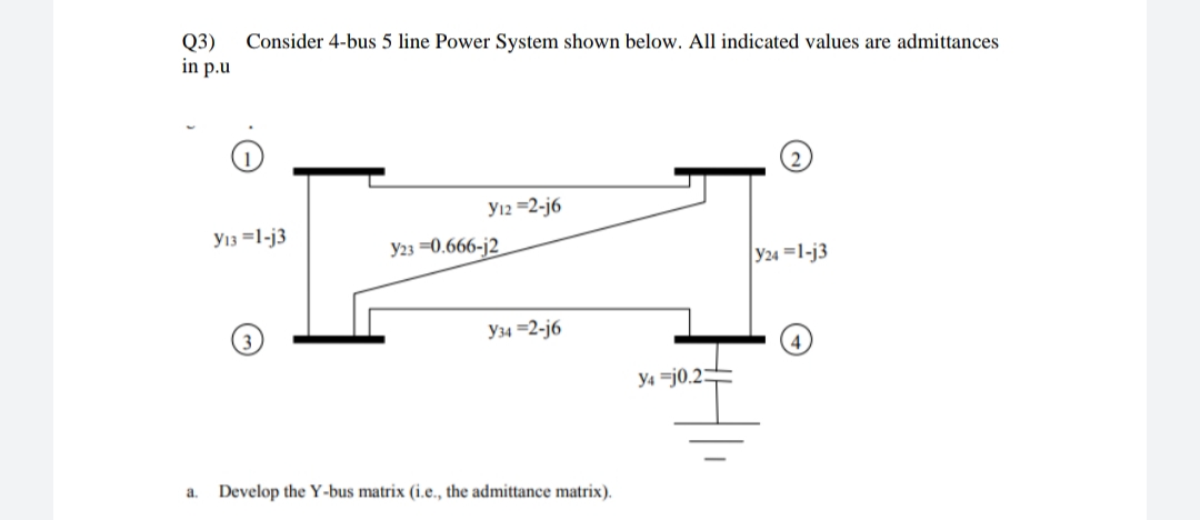
Transcribed Image Text:Q3)
in p.u
Consider 4-bus 5 line Power System shown below. All indicated values are admittances
Y12 =2-j6
Y13 =1-j3
Y23 =0.666-j2
Y24 =1-j3
Y34 =2-j6
y4 =j0.2:
a.
Develop the Y-bus matrix (i.e., the admittance matrix).
Expert Solution
This question has been solved!
Explore an expertly crafted, step-by-step solution for a thorough understanding of key concepts.

This is a popular solution!

Trending now
This is a popular solution!

Step by step
Solved in 2 steps with 1 images

Knowledge Booster


Learn more about
Need a deep-dive on the concept behind this application? Look no further. Learn more about this topic, electrical-engineering and related others by exploring similar questions and additional content below.Recommended textbooks for you
Power System Analysis and Design (MindTap Course …
Electrical Engineering
ISBN:
9781305632134
Author:
J. Duncan Glover, Thomas Overbye, Mulukutla S. Sarma
Publisher:
Cengage Learning
Power System Analysis and Design (MindTap Course …
Electrical Engineering
ISBN:
9781305632134
Author:
J. Duncan Glover, Thomas Overbye, Mulukutla S. Sarma
Publisher:
Cengage Learning