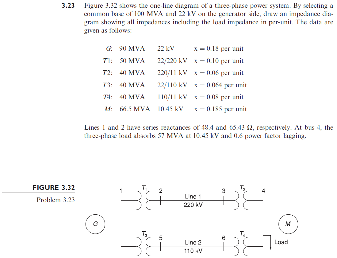
Figure 3.32 shows the one-line diagram of a three-phase power system. By selecting a common base of 100 MVA and 22 kV on the generator side, draw an impedance dia- gram showing all impedances including the load impedance in per-unit. The data are given as follows: 3.23 G: 90 MVA 22 kV x = 0.18 per unit T1: 50 MVA 22/220 kV x = 0.10 per unit T2: 40 MVA 220/11 kV x = 0.06 per unit Т3: 40 MVA 22/110 kV x = 0.064 per unit T4: 40 MVA 110/11 kV X = 0.08 per unit M: 66.5 MVA 10.45 kV x = 0.185 per unit Lines 1 and 2 have series reactances of 48.4 and 65.43 N, respectively. At bus 4, the three-phase load absorbs 57 MVA at 10.45 kV and 0.6 power factor lagging. FIGURE 3.32 T, 1 2 4 Line 1 Problem 3.23 220 kV M 6 Line 2 Load 110 kV
Figure 3.32 shows the one-line diagram of a three-phase power system. By selecting a common base of 100 MVA and 22 kV on the generator side, draw an impedance dia- gram showing all impedances including the load impedance in per-unit. The data are given as follows: 3.23 G: 90 MVA 22 kV x = 0.18 per unit T1: 50 MVA 22/220 kV x = 0.10 per unit T2: 40 MVA 220/11 kV x = 0.06 per unit Т3: 40 MVA 22/110 kV x = 0.064 per unit T4: 40 MVA 110/11 kV X = 0.08 per unit M: 66.5 MVA 10.45 kV x = 0.185 per unit Lines 1 and 2 have series reactances of 48.4 and 65.43 N, respectively. At bus 4, the three-phase load absorbs 57 MVA at 10.45 kV and 0.6 power factor lagging. FIGURE 3.32 T, 1 2 4 Line 1 Problem 3.23 220 kV M 6 Line 2 Load 110 kV

Power System Analysis and Design (MindTap Course List)
6th Edition
ISBN:9781305632134
Author:J. Duncan Glover, Thomas Overbye, Mulukutla S. Sarma
Publisher:J. Duncan Glover, Thomas Overbye, Mulukutla S. Sarma
Chapter3: Power Transformers
Section: Chapter Questions
Problem 3.23P: Figure 3.32 shows the oneline diagram of a three-phase power system. By selecting a common base of...

Related questions

Question
100%
Subject: Power
Book Name: Power System Analysis and Design,. Fifth Edition. J. Duncan Glover, Mulukutla S. Sarma, and Thomas J
Page: 147
problem no: 3.23
Transcribed Image Text:Figure 3.32 shows the one-line diagram of a three-phase power system. By selecting a
common base of 100 MVA and 22 kV on the generator side, draw an impedance dia-
gram showing all impedances including the load impedance in per-unit. The data are
given as follows:
3.23
G: 90 MVA
22 kV
x = 0.18 per unit
T1: 50 MVA
22/220 kV
x = 0.10 per unit
T2:
40 MVA
220/11 kV
X = 0.06 per unit
Т3: 40 MVА
22/110 kV x = 0.064 per unit
T4:
40 MVA
110/11 kV
x = 0.08 per unit
M:
66.5 MVA
10.45 kV
x = 0.185 per unit
Lines 1 and 2 have series reactances of 48.4 and 65.43 N, respectively. At bus 4, the
three-phase load absorbs 57 MVA at 10.45 kV and 0.6 power factor lagging.
FIGURE 3.32
T2
3
4
Line 1
Problem 3.23
220 kV
M
T3
Ta
6
Line 2
Load
110 kV
Expert Solution
This question has been solved!
Explore an expertly crafted, step-by-step solution for a thorough understanding of key concepts.

This is a popular solution!

Trending now
This is a popular solution!

Step by step
Solved in 3 steps with 3 images

Knowledge Booster


Learn more about
Need a deep-dive on the concept behind this application? Look no further. Learn more about this topic, electrical-engineering and related others by exploring similar questions and additional content below.Recommended textbooks for you
Power System Analysis and Design (MindTap Course …
Electrical Engineering
ISBN:
9781305632134
Author:
J. Duncan Glover, Thomas Overbye, Mulukutla S. Sarma
Publisher:
Cengage Learning
Power System Analysis and Design (MindTap Course …
Electrical Engineering
ISBN:
9781305632134
Author:
J. Duncan Glover, Thomas Overbye, Mulukutla S. Sarma
Publisher:
Cengage Learning