Q3)Analyse the given circuit by applying superposition

Delmar's Standard Textbook Of Electricity
7th Edition
ISBN:9781337900348
Author:Stephen L. Herman
Publisher:Stephen L. Herman
Chapter2: Electrical Quantities And Ohm’s Law
Section: Chapter Questions
Problem 1PA: You are an electrician on the job. The electrical blueprint shows that eight 500-W lamps are to be...

Related questions

Question
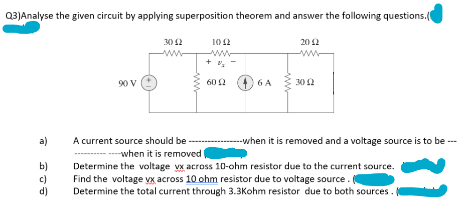
Transcribed Image Text:Q3)Analyse the given circuit by applying superposition theorem and answer the following questions.(
a)
b)
c)
d)
90 V
30 92
www
A current source should be
www
10 92
www
+ Ux
60 92
6 A
www
20 92
ww
30 92
--when it is removed and a voltage source is to be ---
----when it is removed
Determine the voltage vx across 10-ohm resistor due to the current source.
Find the voltage vx across 10 ohm resistor due to voltage source.
Determine the total current through 3.3Kohm resistor due to both sources.
Expert Solution
This question has been solved!
Explore an expertly crafted, step-by-step solution for a thorough understanding of key concepts.

Step by step
Solved in 3 steps with 2 images

Knowledge Booster


Learn more about
Need a deep-dive on the concept behind this application? Look no further. Learn more about this topic, electrical-engineering and related others by exploring similar questions and additional content below.Recommended textbooks for you
Delmar's Standard Textbook Of Electricity
Electrical Engineering
ISBN:
9781337900348
Author:
Stephen L. Herman
Publisher:
Cengage Learning
Delmar's Standard Textbook Of Electricity
Electrical Engineering
ISBN:
9781337900348
Author:
Stephen L. Herman
Publisher:
Cengage Learning