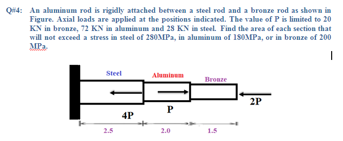
Q#4: An aluminum rod is rigidly attached between a steel rod and a bronze rod as shown in Figure. Axial loads are applied at the positions indicated. The value of P is limited to 20 KN in bronze, 72 KN in aluminum and 28 KN in steel. Find the area of each section that will not exceed a stress in steel of 280MPA, in aluminum of 180MPA, or in bronze of 200 MPa. Steel Aluminum Bronze 2P P 4P to 2.5 2.0 1.5
Q: 6- Find Aa/As for fig. shown below when the steel rod and aluminum carried a concrete slab and the…
A: Given: Es (steel)=200 GPaEa (aluminium)=70 GPaLs=3 mLa=6 m
Q: H.W.6: A hollow circular cold-rolled bronze [G = 6,500 ksi] tube (1) with an outside diameter of…
A:
Q: Axial loads are applied with rigid bearing plates to the solid cylindrical rods shown in the figure.…
A: Diameter of each section can be calculated by calculating net force on each section . 1. Calculate…
Q: The assembly in Figure consists of a light rigid bar AB, pinned at O, that is attached to the ste…
A: Given Deflection = 5 mm Area of steel = 250 mm2 Area of aluminum = 300 mm2 Find…
Q: 2. A compound bar consisting of bronze, aluminum, and steel segments is loaded axially as shown in…
A:
Q: 4. An aluminum rod is rigidly attached between a steel rod and a bronze rod as shown in Fig. Axial…
A:
Q: For the figure shown, have the following information: Bar (1) made of bronze Bar (2) made of…
A:
Q: An aluminum rod is rigidly attached between a steel rod and a bronze rod as shown in the figure.…
A: Draw a free body diagram for the beam. Here, R is the horizontal reaction at the fixed support.…
Q: Rigid bar BC is supported by aluminum rod (1) and bronze rod (2), as shown in the figure. Aluminum…
A:
Q: A load P is supported by a structure consisting of rigid bar ABC, two identical solid bronze [E =…
A:
Q: For the beam shown in the figure, the allowable bearing stress for the material under the supports…
A: Draw a free body diagram for the problem. Equate the net moment about A to zero for static…
Q: A load P is supported by a structure consisting of rigid bar ABC, two identical solid bronze [E =…
A:
Q: An aluminium rod is attached between a steel rod and a bronze rod as shown in Figure-3. The axial…
A:
Q: A homogeneous 800 kg bar AB is supported at either end by a cable as shown in Fig. P-105. Calculate…
A: Stress is the internal resisting force that offers strength to the applied force. If the stress…
Q: The assembly shown in Figure consists of an aluminum tube AB having a cross-sectional area of 400…
A:
Q: 5. A compound bar containing bronze and steel segments carries the axial loads as shown in Figure…
A:
Q: A steel tube is rigidly attached between an aluminum rod and a bronze rod as shown in the figure.…
A:
Q: The segment AB of the steel torsion bar is a cylindrical tube of constant 2-mm wall thickness.…
A:
Q: A vertical steel bar shown in figure Q1 is subjected to a compressive load of 75 kN. If the stress…
A: Given data: F=75 kNδ=0.04 mmE=200 GN/m2 Need to determine the cross-sectional dimensions and length…
Q: 5. An angle bracket ABC is restrained by a high- strength steel wire CD, and it supports a load P at…
A:
Q: An aluminum rod is rigidly attached between a steel rod and a bronze rod as shown in the figure.…
A: Answer: (1) Considering steel : P = 12600 N. (2) Considering aluminum : P = 30400 N. (3) Considering…
Q: 1. The 30.0-mm-diameter steel rod whose E = 150.0 GPa is subjected to the axial forces shown in the…
A:
Q: An aluminum rod is rigidly attached between a steel rod and a bronze rod as shown in the figure.…
A: Consider the Free Body Diagram: Force acting on Bronze rod:FCD=2PStress in Bronze…
Q: Axial loads are applied with rigid bearing plates to the solid cylindrical rods shown in the figure.…
A:
Q: 3. A rod is composed of an aluminum section rigidly attached between steel and bronze sections, as…
A:
Q: 4: rod and a bronze rod as shown in Figure. Axial loads are applied at the positions indicated. The…
A:
Q: The assembly in Figure below consists of a light rigid bar AB, pinned at O, that is attached to the…
A: Given:AB=0.75mOB=1.5m∆=5mmFor steelAst=250mm2E=200 GPaFor aluminiumL=BC=2mAal=300mm2E=70 GPaTo find…
Q: 3. Given the following data of the figure shown : P= 3.5 KN, L, = L, = L, = 1.5 m Strut BC = 100 mm…
A:
Q: As shown in the figure below, three steel wires, each 0.05 in² in area, are used to lift a load W =…
A: L1 = 64.98 ft L2 = 64.99 ft L3 = 65.00 ft A = area of each wire = 0.05 in2 W = 1300 lb It is…
Q: Bronze A = 300mm² E = 83 GPa 2.00 m %3D Steel A = 600mm? E = 200 GPa 1.00 m A 0.60m 1.00 m 1.00m
A:
Q: Axial loads are applied with rigid bearing plates to the solid cylindrical rods shown in the figure.…
A:
Q: A compound bar consisting of bronze, aluminium and steel segments is loaded axially as shown in…
A:
Q: 2. A horizontal bar of negligible mass, hinged at A in the figure and assumed rigid, is supported by…
A: RS, RB are tensions in steel and bronze Rax and Ray are the rections at pin joint A ∆S ,∆B are…
Q: C Rod 45° 7' Steel Plate A 12' P.
A: FBD of the given system is mentioned above Volume of steel plate= 12×7×1= 84 inch3= 0.0486111 ft3…
Q: An aluminum rod is rigidly attached between a steel rod and a bronze rod as shown in figure. Axial…
A:
Q: The rigid bar of negligible weight is supported as shown in the figure. If W=60 kN, compute the…
A: Force acting in the vertical direction is vA+Ts+TB=60⋯⋯⋯(1) Moment about point A is…
Q: 2.16 A compound bar consisting of bronze, aluminum, and steel segments is loaded axially as shown in…
A: Consider a prismatic bar having length L, area of cross-section A, Modulus of Elasticity E is…
Q: Q2-A wall bracket as shown in figure below, is subjected to a pull load of P=45KN at 60° to the…
A: Stress: When a component or a part is subjected to any external force, a resisting force will be…
Q: b) An aluminium rod is attached between a steel rod and a bronze rod as shown in Figure- 3. The…
A: Given data: The area of steel bar is As=550 mm2 The area of Aluminium bar is Aal=400 mm2 The area of…
Q: The rigid bar AB as shown in Figure Q1(a) is supported by a steel road AC having a diameter of 22 mm…
A: Diameter of steel rod = 22 mm Cross section area of aluminium block = 2000 mm2 Diameter of pin = 20…
Q: An aluminum rod is rigidly attached between a steel rod and a bronze rod as shown in Figure. Axial…
A:
Q: Q2/ For assembly shown in the figure. Determine the stress in each of the two vertical rods if the…
A:
Q: A rod is composed of an aluminum section rigidly attached between steel and bronze sections, as…
A: The Answer is Below
Q: Q3 // Two 300 mm x 16 mm plates are riveted together with 25 mm diameter rivets double cover butt…
A: Given: Diameter of the each rivet: d= 25 mm Width of each plate, b = 300 mm and thickness of the…
Q: Q#4: An aluminum rod is rigidly attached between a steel rod and a bronze rod as shown in Figure.…
A:
Q: An aluminum rod is rigidly attached between a steel rod and a bronze rod as shown in the figure…
A: GIVEN DATA- FOR STEEL AREA=500mm2 , STRESS=200MPa FOR AL AREA=400mm2 , STRESS=115MPa FOR BRONZE…
Q: A compound bar consisting of bronze, aluminum, and steel segments is loaded axially as shown in the…
A:
Q: A steel pipe (1) is attached to an aluminum pipe (2) at flange B. Both steel pipe (1) and aluminum…
A: Given, Cross sectional Area of the pipes, A1=3600 mm2A2=2000 mm2 Lengths, L1=1.8m and L2=1.4m…
Q: 3. Given the following data of the figure shown: P= 5.5 KN, L, = L, = L, = 2.5 m Strut BC = 100 mm…
A: P=5.5kN L1=L2=L3=2.5m
Q: 2. The tank shown in the figure is fabricated from 10mm steel plate. Determine the maximum…
A: As per our guidelines we are supposed to answer only one question. Kindly repost other questions as…
Step by step
Solved in 2 steps with 4 images
- A capped cast-iron pipe is compressed by a brass rod, as shown. The mil is turned until it is just snug, then add an additional quarter turn to pre-compress the cast-iron pipe. The pitch of the threads of the bolt ap = 52 mils (a mil is one-thousandth of an inch). Use the numerical properties provided. (a) What stresses a and arwill be produced in the cast-iron pipe and brass rod. respectively, by the additional quarter turn of the nut? (b) Find the bearing stress ahbeneath the washer and the shear stress t(in the steel cap.Solve the preceding problem if F =90 mm, F = 42 kN, and t = 40°MPaA hollow, circular, cast-iron pipe (Ec =12,000 ksi) supports a brass rod (Ec= 14,000 ksi} and weight W — 2 kips, as shown. The outside diameter of the pipe is dc= 6 in. (a) If the allowable compressive stress in the pipe is S00O psi and the allowable shortening of the pipe is 0.02 in., what is the minimum required wall thickness trmm? (Include the weights of the rod and steel cap in your calculations.) (b) What is the elongation of the brass rod Srdue to both load Wand its own weight? (c) What is the minimum required clearance h?
- A two-story building has steel columns AB in the first floor and BC in the second floor, as shown in the figure. The roof load P:equals 400 KN, and the second-floor load P-, equals 720 kN. Each column has a length L = 3.75 m. The cross-sectional areas of the first- and second-floor columns are 11,000 mm" and 3900 mm", respectively. (a) Assuming that E = 206 GPa. determine the total shortenings aof the two columns due to the combined action of the loads Ptand P,. (b) How much additional load P0can be placed at t he top of t he column (point C) if t he total shortening: SACis not to exceed 4.0 mm?5. A bronze rod is rigidly attached between a aluminum rod and a steel rod as shown. Axial loads are applied at the positions indicated. Find the maximum allowable value of P that will not exceed a stress in steel of 140MPa, in aluminum of 90MPa or in bronze of 100MPa.A rectangular steel block is 3 inches long in the x direction, 2 inches long in the y direction, and 4 inches long in the z direction. The block is subjected to a triaxial loading of three uniformly distributed forces as floows; 48 kips tension in the x directio, 60 kips compression in the y direction, and 54 kips tension in the z direction. If v = 0.30 and E = 29 x 106 psi, determine the single uniformly distributed load in the x direction that would produce the same deformation in the y direction as the original loading.
- A load P is supported by a structure consisting of rigid bar ABC, two identical solid bronze [E = 15,000 ksi] rods, and a solid steel [E = 30,000 ksi] rod. The bronze rods (1) each have a diameter of 0.75 in. and they are symmetrically positioned relative to the center rod (2) and the applied load P. Steel rod (2) has a diameter of 0.50 in. The normal stress in the bronze rods must be limited to 14 ksi, and the normal stress in the steel rod must be limited to 18 ksi. Determine: (a) the maximum downward load P that may be applied to the rigid bar.(b) the deflection of the rigid bar at the load determined in part (a).The turnbuckles in the diagram shown are tightened until the compression block DB exerts a force of 12,365lb on the beam at B. Member DB is a hollow shaft with an inner diameter of 1.0 inch and outer diameter of 2 inches. Rods AD and CD each have cross-sectional areas of 1.1 square inches. Pin C has a diameter of 0.78 inch. Determine the following: a.The axial stress, in psi, in BD. b.The axial stress, in psi, in CD.c.The shearing stress, in psi, in pin C.Find the maximum value of P that will not exceed a stress in steel of 113 MPa, in aluminum of 91 000 KPa, or in bronze of 110 MPa if the aluminum rod is rigidly attached between a steel rod and a bronze rod.
- A-36 Aluminium rod shown in figure Q1a is 2.5 m long and must not stretch more than 1.5 mm when an 10.5 kN load is applied to it. Knowing that E = 75 GPa, determine (i) the smallest diameter rod which should be used, (ii) the corresponding normal stress caused by the load.An aluminium rod is attached between a steel rod and a bronze rod as shown in Figure-3. The axial loads are applied at the positions indicated.Determine the maximum value of P that will not exceed a stress in steel of 140 MPa, in aluminium of 90 MPa, and in bronze of 100 MPa.Axial loads are applied with rigid bearing plates to the solid cylindrical rods shown. The normal stress in aluminum rod (1) must be limited to 19 ksi, the normal stress in brass rod (2) must be limited to 22 ksi, and the normal stress in steel rod (3) must be limited to 13 ksi. Determine the minimum diameter required for each of the three rods. Assume P = 7 kips, Q = 2 kips, R = 16 kips and S = 20 kips.