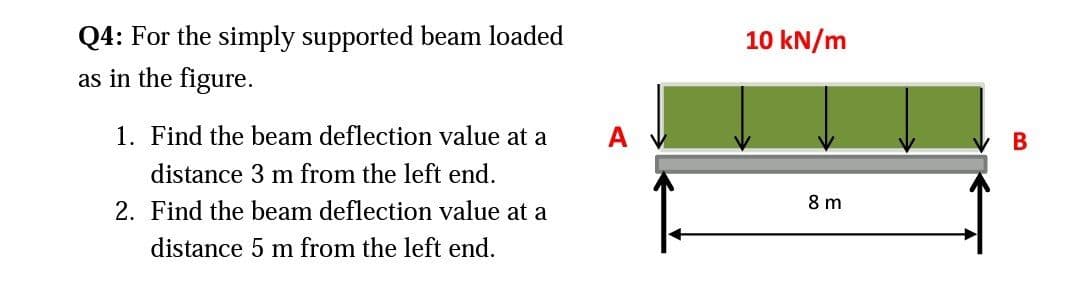
Q4: For the simply supported beam loaded as in the figure. 10 kN/m 1. Find the beam deflection value at a A distance 3 m from the left end. 2. Find the beam deflection value at a 8 m distance 5 m from the left end.


Q: Q) A simply supported beam shown is loaded as shown in figurel-1. It has the cross section as shown…
A:
Q: A cantilever beam ACB supports two concentrated loads P, and P2, as shown in the following figure.…
A: Draw a diagram for the problem. Here, x is the distance of the cross-section at which the bending…
Q: Consider a wooden rectangular slab of mass M, length L, and width W nailed vertically to a wall. The…
A:
Q: Q) A simply supported beam shown is loaded as shown in figurel-1. It has the cross section as shown…
A:
Q: A cantilever beam is free of support at point A and is clamped at the point B, as shown in the…
A: It is required to determine support reaction force at B
Q: A simply supported beam ABCD is subjected to a linearly distributed load, with wo = 100 N/m, two…
A:
Q: A cantilever beam is free of support at point A and is clamped at the point B, as shown in the…
A:
Q: The cantilever beam AB shown in the figurehas an extension BCD attached to its free end.A force P…
A:
Q: A 5.15-N beam of uniform density is 1.70 m long. The beam is supported at an angle of 35.0° by a…
A:
Q: A countershaft carrying two V-belt pulleys is shown in the figure. Pulley A receives power from a…
A: Provided that at bearing B the tension at the loose side is 15 percent of tension at the tight side.…
Q: b) A cantiliver beam ABC shown in Figure Q3(b) has a span length of L m carry a point load P at…
A:
Q: In the following figure, a uniform beam of length 6.00 meters is supported by a horizontal cable and…
A:
Q: The cantilever beam in the figure has a fixed support at A and is under the actions of a uniformly…
A:
Q: The extended beam ABC in the figure below is pin-supported at A and roller-supported at B. For the…
A:
Q: In the figure, aluminum [E = 60 GPa] links (1) and (2) support rigid beam ABC. Link (1) has a…
A:
Q: 8 em cm 1 cm 8icm 1 m 2m 1m Prob. 11.9
A:
Q: P4.9 In Figure P4.9, rigid beam AB is subjected to a distributed load that increases linearly from…
A:
Q: In the figure, aluminum [E = 60 GPa] links (1) and (2) support rigid beam ABC. Link (1) has a…
A: Data given - a = 1380 mm, b = 760 mm, L₁= 2570 mm, and L₂ = 4650 mm. P = 32 kN A2 = 430 mm2 A1 =…
Q: For the simply supported steel beam [E = 200 GPa; I = 129 x 10^6 mm^4] shown in the figure use the…
A: A pin support will exert both horizontal and vertical components of a reaction. The support A is pin…
Q: Figure Q1 shows a cantilever beam ABCDE subjected to a uniformly distributed load, w from points B…
A: The loading diagram is Here, the UDL is extended upto point E and a upward counterbalance UDL from…
Q: 10.4-13 Beam ABC is fixed at support A and rests (at point B) upon the midpoint of beam DE (see the…
A: The deflection diagram of the beam without considering beam DE is given as, The maximum deflection…
Q: H.W. 2 / Find the reactions of the simply supported beam shown in Figure below 300kN 30kNm 15kNm .B…
A: Answer: (a) The reactions at the hinge support A: (RA)x = 180 kN ; (RA)y = 165 kN. (b) The reactions…
Q: Figure Q2 shows the free body diagram of a 10 m long beam AD of uniform cross-section, simply…
A:
Q: A uniform, horizontal beam of mass M 30 kg and length L its left end, as in the figure. The beam is…
A: Find the maximum mass of box.
Q: Q-2 For the simply supported steel beam [E = 200 GPa; I = 129 × 106 mm4 ] shown in Figure below,…
A:
Q: The beam will fail if the maximum bending moment reaches 900 Nm or the maximum shear force becomes…
A:
Q: 3. A rectangular beam has an extended cantilever beam the is attached at the end of the beam. A…
A: As per given question We have to determine What is the angle of twist of the beam if the length of…
Q: The extended beam ABC in the figure below is pin-supported at A and roller-supported at B. For the…
A:
Q: J: A beam is 10.5 m in length and loaded as shown in Figure Q4. If the deflection in the…
A:
Q: 7. Calculate the displacement at the free end of the inclined beam shown in Figure P3.7.Repeat the…
A:
Q: 10.4-13 Beam ABC is fixed at support A and rests (at point B) upon the midpoint of beam DE (see the…
A: The general expression for deflection at any point x in a cantilever beam in that the load P is…
Q: For the simply supported beam shown in the figure, if (q=30 KN/m) and (L=6m), then, the point of…
A: Consider the free body diagram of the beam as shown below. The distributed load can be assumed to…
Q: Q A simply supported beam shown is loaded as shown in figurel-1. It has the cross section as shown…
A:
Q: Figure 6 shows a beam of length 8 m, simply supported at each end, and loaded with a point load of…
A: Consider upward force & CW moment as (+)ve and downward force & CCW moment as (-)ve. Net…
Q: A cantilever beam has a length L and is loaded by a triangularly distributed load of maximum…
A: Given Data The length of the beam is: L The reaction force acting at B is: RB The reaction force…
Q: A cantilevered bar in the figure is acted up on by a system of forces Fx =75 lb, Fy 200 lb, and Fz =…
A: according to the given details
Q: A cantilever beam is free of support at point A and is clamped at the point B, as showi in the…
A:
Q: 9.3-12Derive the equation of the deflection curve for a cantilever beam AB supporting a load P at…
A:
Q: 9.4-7 A beam on simple supports is subjected to a parabolically distributed load of intensity q(x) =…
A:
Q: A beam of uniform flexural stiffness El and span L is simply-supported at its ends as shown in…
A:
Q: A) Calculate the deflection and rotation at point (c) for the beam showing in figure by using unit…
A:
Q: Q) A simply supported beam shown is loaded as shown in figurel-1. It has the cross section as shown…
A:
Q: The extended beam ABC in the figure below is pin-supported at A and roller-supported at B. For the…
A:
Q: A steel beam type W 250x80 is subjected to a concentrated force of 100kN at B as shown in the…
A:
Q: A cantilever beam carries a trapezoidal distributed load ( see figure) . Let wB=2.5 kN/ m, wA=…
A: The deflection and the angle of the free end of cantilever beam when subjected to uniformly…
Q: A cantilever beam AB of length L and uniform flexural rigidity El is shown in Fig. Q4(a). It is…
A: For the uniformly distributed load on the whole span; Let the origin be at the fixed end, At a…
Q: Beam ABC in the figure is loaded as shown. Determine the support reactions. B0KN 20KN/m -30kN 60KN-m…
A: Consider the free-body diagram is shown below, The load due to UDL is given as, =20 kN×2 m=40 kN·m…
Q: For the simply supported steel beam [E = 200 GPa; I = 129 x 10^6 mm^4] shown in the figure use the…
A:
Q: (a) Square Beam AB having the circular hollow cross-section as shown in Figure Qla and it is loaded…
A: Since you have asked multiple questions, we will solve the first question for you. If you want any…
Q: please answer the question
A: MAB=-400×108=-500 kN-mMBA=500 kN-mMBC=30×10212=30×10012=-250 kN-mMCB=250 kN-m

Step by step
Solved in 3 steps with 3 images

- A counterclockwise moment M0acts at the midpoint of a fixed-end beam ACB of length L (see figure). Beginning with the second-order differential equation of the deflection curve (the bendingmoment equation), determine all reactions of the beam and obtain the equation of the deflection curve for the left-hand half of the beam. Then construct the shear-force and bending-moment diagrams for the entire beam, labeling all critical ordinales. Also, draw the deflection curve for the entire beam.-17 A cantilever beam AB is acted upon by a uniformly distributed moment (bending moment, not torque) of intensity m per unit distance along the axis of the beam (see figure). Derive the equation of the deflection curve and then obtain formulas for the deflection Band angle of rotation Bat the free end. Use the second-order differential equation of the deflection curve.A fixed-end beam AB of a length L is subjected to a uniform load of intensity q acting over the middle region of the beam (sec figure). Obtain a formula for the fixed-end moments MAand MBin terms of the load q, the length L, and the length h of the loaded part of the beam. Plot a graph of the fixed-end moment MAversus the length b of the loaded part of the beam. For convenience, plot the graph in the following nondimensional form: MAqL2/l2versusbL with the ratio b/L varying between its extreme values of 0 and 1. (c) For the special case in which ù = h = L/3, draw the shear-force and bending-moment diagrams for the beam, labeling all critical ordinates.
- A cantilever beam model is often used to represent micro-clectrical-mechanical systems (MEMS) (sec figure}. The cantilever beam is made of polysilicon (E = 150 GPa) and is subjected to an electrostatic moment M applied at the end of the cantilever beam. 1 f dimensions arc h — 2 [im, h — 4 ^m, and L = 520 ^mt find expressions for the tip deflection and rotation of the cantilever beam in terms of moment M.A cantilever beam has a length L = 12 ft and a rectangular cross section (b = 16 in., h = 24 in.), A linearly varying distributed load with peak intensity q0acts on the beam, (a) Find peak intensity q0if the deflection at joint B is known to be 0.18 in. Assume that modulus E = 30,000 ksi. (b) Find the location and magnitude of the maximum rotation of the beam.The beam AB shown in the figure is simply supported at A and B and supported on a spring of stiffness k at its midpoint C. The beam has flexural rigidity EI and length IL. What should be the stiffness k of the spring in order that the maximum bending moment in the beam (due to the uniform load) will have the smallest possible value?
- -22 Derive the equations of the deflection curve for a simple beam AB with a distributed load of peak intensity q0acting over the left-hand half of the span (see figure). Also, determine the deflection cat the midpoint of the beam. Use the second-order differential equation of the deflection curve.Beam ABC is fixed at support A and rests (at point B) upon the midpoint of beam DE (see part a of the figure). Thus, beam, ABC may be represented as a propped cantilever beam with an overhang BC and a linearly elastic support of stiffness k at point B (see part b of the figure). The distance from A to B is L = 10 ft, the distance from B to C is L/2 = 5 ft, and the length of beam DE is L = 10 ft. Both beams have the same flexural rigidity EI. A concentrated load P = 1700 lb acts at t lie free end of beam ABC. Determine the reactions RA, RB+ and MAfor beam ABC. Also, draw the shear-force and bending-moment diagrams for beam ABC, labeling all critical ordinates.Cantilever beam AB carries an upward uniform load of intensity q1from x = 0 to L/2 (see Fig. a) and a downward uniform load of intensity q from x = L/2 to L. Find q1in terms of q if the resulting moment at A is zero. Draw V and M diagrams for the case of both q and qtas applied loadings. Repeat part (a) for the case of an upward triangularly distributed load with peak intensity q0(see Fig. b). For part (b), find q0, instead of q1
- A simply supported beam (E = 1600 ksi) is loaded by a triangular distributed load from A to C(see figure). The load has a peak intensity q0= 10 lb/ ft, and the deflection is known to be 0.01 in, at point C. The length of the beam is 12 ft, and the ratio of the height to the width of the cross section is (h:b) 2:1, Find the height h; and width h of the cross section of the beam.The compound beam shown in the figure consists of a cantilever beam AB (length L) that is pin-connected to a simple beam BD (length 2L). After the beam is constructed, a clearance c exists between the beam and a support at C, midway between points B and ZX Subsequently, a uniform load is placed along the entire length of the beam. What intensity q of the load is needed to close the gap at C and bring the beam into contact with the support?-9 Derive the equations of the deflection curve for beam ABC with sliding support at A and roller support at B, supporting a uniform load of intensity q acting on the overhang portion of the beam (see figure). Also, determine deflection cand angle of rotation c. Use the fourth-order differential equation of the deflection curve (the load equation).