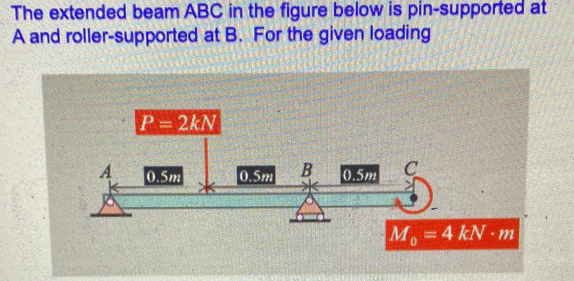
The extended beam ABC in the figure below is pin-supported at A and roller-supported at B. For the given loading P 2kN 0.5m 0.5m 0.5m M 4 kN m


Q: A cantilever beam ACB supports two concentrated loads P, and P2, as shown in the following figure.…
A: Draw a diagram for the problem. Here, x is the distance of the cross-section at which the bending…
Q: Q3) For the circular arch shown in the figure, compute the value of " P" such that the vertical…
A: Write the given values along with suitable variables and draw the FBD for the given question.
Q: _Is4lhVkfYEXQZh-UZqdpqqMbGT. 1/ 2 100% 1) For beam shown below, find reaction forces in supports A &…
A:
Q: The three-bar truss ABC shown in figure part a has a span L = 3 m and is constructed of steel pipes…
A:
Q: In the figure, find the length c of the overhangs so that the beam made of U profile can carry the…
A:
Q: A ec=K L B b→,K 1. (Section)
A:
Q: Figure In the figure shown, a bar ABC with negligible mass carries a 20 kN load and is supported by…
A: the allowable shear stress of the pin in not given to get the diameter of the pin.please put the…
Q: A simply supported beam which has 16 mm height and 8 mm thickness is supported by pin at A and…
A:
Q: 2. As shown in the figure, a rigid beam with negligible mass is pinned at one end and supported by…
A:
Q: 3. A round shaft, 45 mm in diameter, carries a 3500 N load, as shown in the Figure. If the shaft is…
A:
Q: Q.1) For the solid beam ABC shown in figure, is supported by two vertical bars. If a pin support…
A: Given data: - The cross-sectional area of bar BD and CE is A = 720 mm2. The elastic constant for…
Q: A vertical steel bar ABC is pin-supported at its upper end and loaded by a force P,at its lower end.…
A: Given Data The load acting at point E is: P=2.5 kip Distance from A to B is: AB=20 in Distance from…
Q: Q1: The horizontal rigid beam ABCD is supported by vertical bars BE and CF and is loaded by vertical…
A:
Q: |1200 Ib | 1200 Ib 3 ft R2
A: Note: As per bartelby guideline first three subpart are solved. please upload other part separately…
Q: Q1 (a) During construction of a highway bridge, the main girders as shown in Figure Q1(a) are…
A: The maximum bending stress in a girder due to this load is 85 MPa.
Q: A bracket ABCD having a hollow circularcross section consists of a vertical arm AB (L 5 6 ft),a…
A:
Q: During construction of a highway bridge, the main girders as shown in Figure Q5(a) are cantilevered…
A:
Q: In the figure, aluminum [E = 75 GPa] links (1) and (2) support rigid beam ABC. Link (1) has a…
A:
Q: A steel cantilever beam is made of two T-shaped structures welded to each other as shown in the…
A: Given data as per question Allowable stress in tension =150 Mpa Allowable stress in compression =…
Q: In the figure, find the length c of the overhangs so that the beam made of U profile can carry the…
A:
Q: 1. A beam of negligible mass is hinged at support P and has a roller support Q as shown in the…
A: Figure with reaction forces is as below: As Q is hinged joint, it has only reaction which is normal…
Q: Axial Loadings Consider the figure shown. A rigid beam is pinned at one end and supported by two…
A: For solution refer below images.
Q: A flanged wooden shape is used to support the loads shown on the beam. The dimensions of the shape…
A: Answer: (a) The maximum tension bending stress is 1530.2124 psi. (b) The maximum compression bending…
Q: In the figure, find the length c of the overhangs so that the beam made of U profile can carry the…
A: Permissible stress is stress which produces due to pressure or forces which does not exceed the…
Q: A cantilever beam, a UPN 300 section, is subjected to its own weight and a point load at B. Find the…
A: Given data, Allowable stress, σallow =125MPa To find:- Load, P=? The section of the beam is UPN 300…
Q: The homogeneous beam shown in the figure is suspended by a cable at point B and is pin supported at…
A:
Q: 32 - Support reactions will be found in the gerber beam whose loading condition is given in the…
A: Draw a diagram for the problem showing the reactions at supports A, B, and C. Here, Ax and Ay are…
Q: 2. The horizontal rigid beam ABCD is supported by vertical bars BE and CF and is loaded by vertical…
A:
Q: PROBLEMS Figure 1. In the figure shown, a bar ABC with negligible mass carries a 20 kN load and is…
A: Draw FBD
Q: Q1: The horizontal rigid beam ABCD is supported by vertical bars BE and CF and is loaded by vertical…
A:
Q: Figure Q1 shows one ‘L’ shaped beam ACD which is built-in at one end. It is loaded with load F=3 kN…
A:
Q: Problem 1 A stiff horizontal beam weighing 400 N is supported by four helical springs with stiffness…
A: helical springs resist forces when elongated or compressed which is directly proportional to the…
Q: A cantilevered bar in the figure is acted up on by a system of forces Fx =75 lb, Fy 200 lb, and Fz =…
A: according to the given details
Q: The horizontal rigid beam ABCD is supportedby vertical bars BE and CF and is loaded byvertical…
A: Given E = 200 GPa Area, ABE= 11,100 mm2 ACF = 9280 mm2. Find Deflections
Q: P1 B. P2 A -ak b
A:
Q: (B) // The straight beam with distribution load as shown in figure B is simply supported by a pin at…
A:
Q: A Simply Supported beam of 4 m span is in the form of hollow square bar (120x120 mm) as shown in…
A:
Q: *2.2-12 The horizontal rigid beam ABCD is supported by vertical bars BE and CF and is loaded by…
A:
Q: In the figure, the horizontal rigid beam ABCD is supported by vertical bars (1) and (2) and is…
A:
Q: A horizontal beam AB of 1.8-2 cross-sectional dimensions (b X h = 19 mm x 200 mm) is supported by an…
A:
Q: B a
A: "Since the language of the question is not so clear. If you anything else please submit the question…
Q: 35 KN 15 KN 30 KN 10 KN O18 m 1:0 m 0,6 m
A:
Q: Beam AB is supported as shown in Figure below. Tie rod (1) is attached at B and C with double‐ shear…
A:
Q: The Uniform AB brass bar is fixed with support and pin as shown in the figure and has a rectangular…
A:
Q: HOMEWORK: Q1/ A beam carries the loads shown in figure, if the tensile stress must not exceed 20 MPa…
A: Find load P
Q: support reaction forces
A: Given: A plane frame with load 2P as shown in Fig To determine all support reaction Forces
Q: A flanged wooden shape is used to support the loads shown on the beam. The dimensions of the shape…
A: Given Data: Length of the beam, L=16 ft
Q: 40 men D Steel t-200 GPa The rigid beam (ABC) supported by three bars, One from the top and two from…
A:
Q: A simply supported steel beam is subjected to a uniformly distributed load as shown in Figure E5.2.…
A:

Plot the bending moment diagram


Trending now
This is a popular solution!

Step by step
Solved in 2 steps with 2 images


- A cantilever beam(Z, = 6 ft) with a rectangular cross section (/> = 3.5 in., h = 12 in.) supports an upward load P = 35 kips at its free end. (a) Find the state of stress ((7T, o^., and r in ksi) on a plane-stress element at L/2 that is i/ = 8 in. up from the bottom of the beam. Find the principal normal stresses and maximum shear stress. Show these stresses on sketches of properly oriented elements. (b) Repeat part (a) if an axial compressive centroidal load N = 40 kips is added at BSolve the preceding problem for a box beam with dimensions h = 0.5 m, h = 0.18 m, and t = 22 mm. The yield stress of the steel is 210 MPa.Beam AB has an elastic support kR at A, pin support at B, length L, height h (see figure), and is heated in such a manner that the temperature difference T2T1 between the bottom and top of the beam is proportional to the distance from support A. Assume the temperature difference varies linearly along the beam: T2T1=T0x in which T0 is a constant having units of temperature (degrees) per unit distance. Assume the spring at A is unaffected by the temperature change. Determine the maximum deflection max of the beam, Repeat for a quadratic temperature variation along the beam, so T2T1=T0x2 What is max for parts (a) and (b) if kR goes to infinity?
- A simple beam thai is IS ft long supports a uni¬form load of intensity a. The beam is constructed of two angle sections, each L (1 × 4 × 1/2, on either side of a 2 in. x 8 in. (actual dimensions! wood beam (see the cross section shown in the figure part a]. The modulus of elasticity of the s I eel is 10 limes that of the wood, (a) If the allowable stresses in the steel and wood are 12,000 psi and 900 psi. respectively, what is the allow atile load a t. A olc. Disregard the weight of the beam, and see Table F-5(a) of Appendix I ' for I lie dimensions and properties of the angles. (b) Repeal partial if a I in. 10 in. wood Hange tactual dimensions) is added i see figure pallhi b).A simple beam with an overhang is subjected to d point load P = 6kN. If the maximum allowable deflect ion at point C is 0.5 mm, select the lightest W360 section from Table F-l{b) that can be used for the beam. Assume that L = 3 m and ignore the distributed weight of the beam.A propped cantilever beam, fixed at the left-hand end A and simply supported at the right-hand end B, is subjected to a temperature differentia] with temperature T1on its upper surface and T2on its lower surface (see figure).
- A cantilever beam of length L = 2 m supports a load P = 8,0 kN (sec figure). The beam is made of wood with cross-sectional dimensions 120 mm x 200 mm. Calculate the shear stresses due to the load/"at points located 25 mm, 50 mm, 75 mm, and 100 mm from the top surface of the beam. From these results, plot a graph showing the distribution of shear stresses from top to bottom of the beam.A W 12 x 35 steel cantilever beam is subjected to an axial load P = 10 kips and a transverse load V = 15 kips. The beam has length L = 6 ft, (a) Calculate the principal normal stresses and the maximum shear stress for an clement located at C near the fixed support. Neglect the weight of the beam, (b) Repeat Part a for point D which is 4 in. above point C (see figure). See Table F-l(a), Appendix F, for beam properties.A steel bracket of solid circular cross section is subjected to two loads, each of which is P = 4.5 kN at D (see figure). Let the dimension variable be b = 240 mm. Find the minimum permissible diameter dmaxof the bracket if the allowable normal stress is 110 M Pa. Repeat part (a), including the weight of the bracket. The weight density of steel is 77.0 kN/m3.
- A steel plate (called a cover ploie) having cross-sectional dimensions 6,0 in. × 0.5 in. is welded along the full length of the bottom flange of a W 12 × 50 wide-flange beam (sec figure, which shows the beam cross section). What is the percent increase in the smaller section modulus (as compared to the wide-flange beam alone)?Each girder of the lift bridge (sec figure) is 180 ft long and simply supported at the ends. The design load for each girder is a uniform load of intensity 1,6 kips/ft. The girders are fabricated by welding three steel plates to form an I-shaped cross section (see figure) having section modulus S = 3600 in3. What is the maximum bending stress rmaxin a girder due to the uniform load?A square wood platform is 8 ft × 8 ft in area and rests on masonry walls (see figure). The deck of the platform is constructed of 2-in. nominal thickness tongue-and-groove planks (actual thickness 1.5 in.; sec Appendix CL) supported on two S-ft long beams. The beams have 4 in. × (i in. nominal dimensions (actual dimensions 3.5 in. × 5.5 in.). The planks arc designed to support a uniformly distributed load n ( lb/ft" i acting over the entire top surface of the platform. I be allowable bending stress for the planks is 2400 psi and the allowable shear stress is 100 psi. W ben analyzing the planks, disregard their weights and assume that their reactions are uniformly distributed over the top surfaces of the supporting beams. (a) Determine the allowable platform load Mr. (lb/ft2) based upon the bending stress in the planks. (b) Determine the allowable platform load if-. (lb/ft-) based upon the shear stress in the planks. (c) Which of the preceding values becomes the allowable load alolow on the platform? Hints: Use care in constructing the loading diagram for the planks, noting especially that the reactions are distributed loads instead of concentrated loads. Also, note that the maximum shear forces occur at the inside faces of the supporting beams.