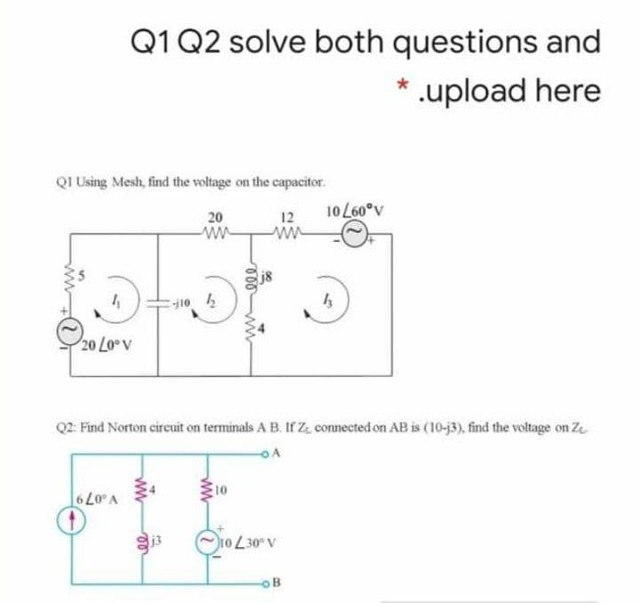
QI Using Mesh, find the voltage on the capacitor. 20 10 L60°v 12 ww j8 20 Lo v


Q: 2. A 137 pF capacitor is connected to a voltage source such that v.(t) = 12e-24V ,t20 and v.(t) = 12…
A: Given data, C= 137 pF = 137×10-12 F Vct=12e-2t V, t≥0 and Vct=12 V, t<0
Q: Q1. For I=1,e*which is best represented by the following data t(msec)= 0 4 8 10 12 14 16 I(HA)= 5 3…
A: Here, we have given an RC circuit. We have given some tabular data where the value of currents at…
Q: The voltage across a capacitor with capacitance of 0.05 µF is given by v(t) = cos(27 × 2000t) u(t)…
A: It is given that: C=0.05 μFvt=cos2π×2000tut
Q: II. Given a voltage waveform below. Find the following: (a) Vp, (b) Vave, (c) VeFf, (d) period, (e)…
A: As per our guidelines, we are supposed to answer only first question. Kindly repost the other…
Q: 40 μF H 10 μF 10 μF 35 μF 5 μF 20 μF 15 μF 15 μF
A:
Q: Vi 180290 V %3D L = 30jN e C,=-30jN %3D C1 L1 A lll R1 V1 15 Q
A:
Q: Four capacitors are connected as shown in the figure below. (C = 16.0 µF.) %3D 3.00 µF th |20.0 µF a…
A: if the Capacitance is C Charge is Q and the voltage is V then the relation between the charge Q and…
Q: Determine the current that flows through an 8 Q resistor connected to a voltage source Us = 110 cos…
A:
Q: 30. A 150-Hz, 25 mA AC current flows in a circuit containing a 20-microfarad capacitor. What is the…
A: To find the voltage drop across a capacitor, we need to find the capacitive reactance Xc. The…
Q: 470pF: 1nF
A: Capacitance By definition, “The property of storing Electricity in the form of Electro-static field…
Q: A 15 mH inductor is in series with a parallel combination of 80 ohm resistor and 20 microFarad…
A:
Q: The current is in the 30 mH inductor is 10cos (10 000t +30°) m A. Calculate; a) The inductive…
A: Given data, Inductor current, is=10cos10000t+30° mA Inductor, L=30 mH
Q: For the following circuit, assume that it has been in this state for a very long time. Dete the…
A: Given that Electrical network as follows
Q: SITUATION NO. 10 - The voltage across the 1 H inductor is 3e^(-t) V. Assume i(0) = 5 20. Find the…
A:
Q: The voltage and current of an element are i(t) = 3.cos(1000t + 10°) V(t) = 6.cos(1000t – 80°) The…
A: Q(6)SolutionThe voltage and current of an elementarei(t)=3 cos(1000t+10°)A=(3∠10°)Av(t)=6…
Q: 19. Determine the stored energy in the capacitor at t = 4. Assume v(0) = 27 %3! V 3272.22 J 3372.22…
A: From given current equation find the voltage across capacitor . Energy stored in capacitor = 0.5 ×…
Q: Q1. For I=1,e"which is best represented by the following data t(msec)= 0 2 4 8 10 12 14 16 I(HA)= 5…
A: In this question, current I= Io e-t/ tao is given. We need to determine the source voltage, and…
Q: nductor. Plot the results: (Provide your calculations and reasoning for your answer.) Current vs…
A:
Q: Four capacitors are connected as shown in the figure below. (Let C = 20.0 µF.) 3.00 μΕ th. |20.0 μF…
A: Given circuit shown C=20 μF
Q: Given the circuit below and after the current no longer flows C₁ =1 farads C₂ =9 farads C3 =1 farads…
A: Given circuit, C1=1 faradC2=9 faradC3=1 faradV=92 volts
Q: 1. A capacitor of 50 µF capacitance is connected in parallel with a reactor of 22 2resistance and…
A:
Q: 30. A 150 - Hz, 25 mA AC current flows in a circuit containing a 20-microfarad capacitor. What is…
A: Given: I=20mAf=150HzC=20μFwhere I is currentF is frequencyC is capacitance
Q: B- Determine the maximum energy stored in the capacitor of the circuit shown and the energy…
A:
Q: 1. Given the voltage on a 72 µF capacitor is as shown in the graph, plot the current through the…
A:
Q: 5. Determine the complex power for the following cases: a) P = 269 W, Q = 150 VAR (capacitive) b) Q…
A: In this question , we will find complex power for different cases..
Q: Calculate the 25 Ω inductor current using Norton's theorem. 80/60° j30 Ω 20Ω του 70Ω -j70 Ω (…
A:
Q: 04: a/ Find the elements of ( Z) for the circuit if its capacitance or inductance ? i 20 sin (314 t+…
A: To solve above problem, one should have basic idea about working of AC circuits. In ac circuits…
Q: The current in the capacitor of Assessment Problem 6.2 is 0 for t <0 and 3 cos 50,000t A for t 2 0.…
A:
Q: Find the equivalent capacitance seen at the terminals of the circuit 50 µF 60 µF Ceq 120 µF 70 μ 20…
A:
Q: 50 μF 60 μΕ Ca 70 μ 20 μΕ 120 μF
A:
Q: b) Find the capacitance of a parallel plate capacitor if the area of each plate 0.1 m² and the…
A: Given data: A=0.1 m2d=2 mm= 0.002mk=5
Q: 3 μF 6 μF 7 μF 0.2 μF | * CT b (a) SECTION 10.13 Capacitors in Series and Parallel 44. Find the…
A:
Q: The voltage across a 21-uF capacitor is given by the following function of time, vo Find the Power…
A:
Q: A 1kQ resistor, a 5mH ideal inductor, and a 1nF capacitor are connected in parallel. Find the total…
A:
Q: A capacitor of two parallel plates with area of 4 cm?. The distance between plates is 2mm. The…
A: Here it is asked to find the current through the capacitor where the capacitance value is not given.…
Q: 5. A steady current of 10 A flows into a previously uncharged capacitor for 1.5 ms when th pd…
A: This question belongs to circuit theory . It is based on the concept of charging capacitor and its…
Q: 2. For the current shown on a 4.8 mH inductor, determine and graph the corresponding voltage. i(t)…
A: Find the voltage across the inductor ?
Q: Q: In electrical parallel plate, capacitor surface S=50 cm² and ɛr= 5(1+z) in positive direction.…
A: As given that area of parallel plate S is 50cm2.And dielectric between plate is εr =5(1+z)Assume…
Q: N 15. What is the capacitance of a capacitor with 4.2m² plates cross-sectional area and 0.09m apart…
A:
Q: For V1=71 & 1=0.005, the voltage and current expressions are: (take care of the units) v = =…
A:
Q: 1. What impedance vector 0 – j22 represents: A. A pure resistance. B. A pure inductance. C. A pure…
A:
Q: The current in an inductor L = 220 mH varies according to I = 3.8 sin(80t) A. Find: The induced emf…
A: Given, Inductor, L=220 mH Current in inductor, I=3.8sin80t A Time, t=2.6 ms
Q: 4- The sinusoidal expression of voltage across capacitor in the circuit contain only capacitor is..…
A: 4) Given: C=10 μFi=20sin500t-30° A
Q: Z4956 non-reactive the combined circuit is 500 2, calculate: a) of the capacitor. b) the current in…
A:
Q: Given the circuit shown below, determine the voltage across the capacitor 60 0.25 F HH + Vcdt) 3…
A:
Q: Problem 5.3 Find the total inductance of the circuit shown.
A:
Q: Consider the following system , plot the root locus with all details and find the value of K for…
A: Root Locus-The root locus is the graphical location of roots of the characteristic equation as the…
Q: For the circuit shown in the following figure, if L= 28 H, Vo=13 V, and R= 28 Q, answer the…
A: In the circuit given data is- L=28 HV∘=13 VR=28 Ω In Laplace domain-…
Q: Compute the equivalent capacitance Cegof the network shown: 7 F 4 F 2 F 8 F 5 F 12 F 5 F 1F 2 F HE
A:
Q: b) Find the capacitance of a parallel plate capacitor if the area of each plate is 0.1 m² and the…
A: area of each plate is 0.1 m2 and distance between the plates is 2 mm and dielectric is oil with a…

Step by step
Solved in 2 steps


- From the following circuit diagram. Determine the impedances for all the Circuit elements such as ZR1, ZR2 and so on. For part A the frequency (f) is f = 60Hz & part f = 100Hz. For both parts, you must redraw the circuit diagram, with all the found impedances shown. Show your final answers as phasor with rectangular coordinates. you must show all of your work for the complex math aswell.Show that at a given frequency ω, the circuits will have the same impedance between the terminals a,b ifR1=R21+ω2R22C22,C1=1+ω2R22C22ω2R22C2.2. Find the values of resistance and capacitance that when connectedin series will have the same impedance at 40 krad/s as that of a1000 Ω resistor connected in parallel with a 50 nF capacitor.Use source transformation to determine Vo as a result of the independent contribution from the voltage source Vs=18<90°. Give the answer in rectangular form
- Use the currents method mesh to find the equation iL(t) (consider a linear frequency 60 hz)An industrial plant has a real power demand of 650 kW at a power factor of 0.65 lagging. The power is supplied by a 3-phase line at voltage of 4.16 kV (line to line voltage). You were just hired and your first task is to find the size of capacitors (in μF) required to improve the power factor to 0.95 lagging. The capacitors will be connected in grounded Y. Find- a) Calculations of the apparent power and the reactive power before the connection of the capacitors, b) Calculations of the reactive power, reactance, and capacitance of a capacitor bank required to improve the power factor to 0.95 lagging c) Calculations of the apparent power and the reactive power after the connection of the capacitors. d) Drawing of the power triangle. In your sketch you must show the real, reactive, and apparent power before and after the power factor correction and highlight the reactive power supplied by the capacitor. e) Sketch of the capacitor connection. Note: frequency is 60 Hz.Show that at a given frequency ω, the circuits will have the same impedance between the terminals a,b ifR2=R12+ω2L12R1, L2=R12+ω2L12ω2L1.(Hint: The two circuits will have the same impedance if they havethe same admittance.)2. Find the values of resistance and inductance that when connected inparallel will have the same impedance at 1 krad/s an 8 kΩresistorconnected in series with a 4 H inducto
- A circuit is designed with an AC source of max voltage 12 and frequency 60 Hz. The circuit has a resistance of 1050 Ohms, an inductance of 0.06 Henrys, and a capacitance of 0.009 coulombs per volt. - omega for source in rad/s? - omegaR for circuit? -XL? -XC? -phi in radians? -Z? -imax?Problem Se: Superpositiib and Max Power Transfer. Use Superstition to Determine Pmss to Load RL.In the diagram given below, given the R1=10Ω, R2=3Ω, ZC= -j15Ω, ZL=j7Ω and V=10⌊30° Determine Thevenin’s Equivalent.
- Find: a) I1; b) I2 The frequency is 60Hz. Provide a step by step solution as well as the illustration.Build Circuit 1b in Multisim. Using MultiSim’s Oscilloscope, display and measure the voltages including the phase angles with respect to the input voltage. THIS IS 1b Problem: 1b) For the circuit shown , let R= 1kohm, L1 = 10mH, C1= 50nF. Calculate the values of Z, Phase Shift, I, Vr, Vc, VL , PR, PAPP and Power Factor. Do this for V1= 10 V at 10000Hz. Find resonant frequency. Measure phase shift like so: a) Measure the difference in times of the peaks for the two different waves. b) Divide this difference by the period length. The ratio tells you what fraction of a cycle the time difference is.c) One cycle is 360 degrees (or 2π radians) so multiply the fraction in step 2 by 360 degrees to convert that time difference into a phase shift (degrees)Evaluate the following twiddle factor: W48