Question 2 (a) Figure 3 shows the positive shunt clipper circuit. Analvze., the output ya wavefor the negative of sinusoidal waveform of -10V with suitable diode position. 10 V 10 k2 -10 V Figure 3 (b) Analvze the output voltage va and the output waveform for the configuration shov Figure 4. 100 V Ideal diodes -100 V 2.2 ka Figure 4 (c) Figure 5 shows the Halfwave rectifier. Analyze, the output voltage, Vour. current, I, the waveform of the output, Vout for two circuit above. Given the transformer to ha 12 V rms secondary voltage for the standard 120 V across the primary. Examine the output voltage for the Bridge rectifier with the practical model, and calculate the Inverse Voltage (PIV) required for the diodes. +5 V +100 V- V. 0 IN4001 IN4003 -5V---- -100 V- 1Ok
Question 2 (a) Figure 3 shows the positive shunt clipper circuit. Analvze., the output ya wavefor the negative of sinusoidal waveform of -10V with suitable diode position. 10 V 10 k2 -10 V Figure 3 (b) Analvze the output voltage va and the output waveform for the configuration shov Figure 4. 100 V Ideal diodes -100 V 2.2 ka Figure 4 (c) Figure 5 shows the Halfwave rectifier. Analyze, the output voltage, Vour. current, I, the waveform of the output, Vout for two circuit above. Given the transformer to ha 12 V rms secondary voltage for the standard 120 V across the primary. Examine the output voltage for the Bridge rectifier with the practical model, and calculate the Inverse Voltage (PIV) required for the diodes. +5 V +100 V- V. 0 IN4001 IN4003 -5V---- -100 V- 1Ok

Electricity for Refrigeration, Heating, and Air Conditioning (MindTap Course List)
10th Edition
ISBN:9781337399128
Author:Russell E. Smith
Publisher:Russell E. Smith
Chapter12: Electronic Control Devices
Section: Chapter Questions
Problem 3RQ: Diodes and rectifiers allow current to _________.
flow in one direction only
flow in both...

Related questions
Question
please answer all pleasee
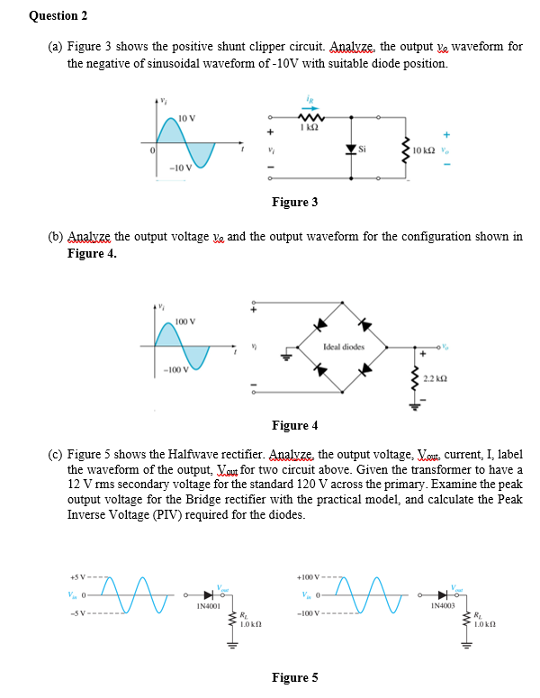
Transcribed Image Text:Question 2
(a) Figure 3 shows the positive shunt clipper circuit. Analze. the output ya waveform for
the negative of sinusoidal waveform of -10V with suitable diode position.
10 V
I k2
10 k2 v.
-10 V
Figure 3
(b) Analvze the output voltage ya and the output waveform for the configuration shown in
Figure 4.
100 V
Ideal diodes
-100 V
2.2 k2
Figure 4
(c) Figure 5 shows the Halfwave rectifier. Analyze, the output voltage, Vou. current, I, label
the waveform of the output, Vout for two circuit above. Given the transformer to have a
12 V rms secondary voltage for the standard 120 V across the primary. Examine the peak
output voltage for the Bridge rectifier with the practical model, and calculate the Peak
Inverse Voltage (PIV) required for the diodes.
+5 V-
+100 V
V. 0
V. 0
IN4001
IN4003
-5 V---
-100 V---
1Okf
1.0k
Figure 5
Expert Solution
This question has been solved!
Explore an expertly crafted, step-by-step solution for a thorough understanding of key concepts.

Step by step
Solved in 2 steps with 4 images

Recommended textbooks for you
Electricity for Refrigeration, Heating, and Air C…
Mechanical Engineering
ISBN:
9781337399128
Author:
Russell E. Smith
Publisher:
Cengage Learning


Delmar's Standard Textbook Of Electricity
Electrical Engineering
ISBN:
9781337900348
Author:
Stephen L. Herman
Publisher:
Cengage Learning
Electricity for Refrigeration, Heating, and Air C…
Mechanical Engineering
ISBN:
9781337399128
Author:
Russell E. Smith
Publisher:
Cengage Learning
Delmar's Standard Textbook Of Electricity
Electrical Engineering
ISBN:
9781337900348
Author:
Stephen L. Herman
Publisher:
Cengage Learning