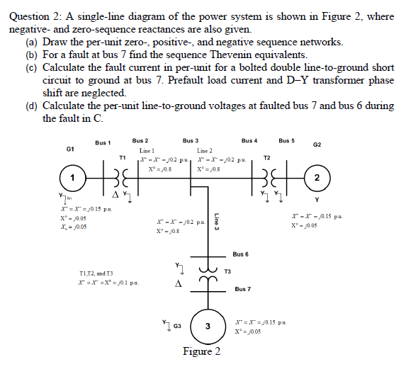
Question 2: A single-line diagram of the power system is shown in Figure 2, where negative- and zero-sequence reactances are also given. (a) Draw the per-unit zero-, positive-, and negative sequence networks. (b) For a fault at bus 7 find the sequence Thevenin equivalents. (c) Calculate the fault current in per-unit for a bolted double line-to-ground short circuit to ground at bus 7. Prefault load current and D-Y transformer phase shift are neglected. (d) Calculate the per-unit line-to-ground voltages at faulted bus 7 and bus 6 during the fault in C.
Question 2: A single-line diagram of the power system is shown in Figure 2, where negative- and zero-sequence reactances are also given. (a) Draw the per-unit zero-, positive-, and negative sequence networks. (b) For a fault at bus 7 find the sequence Thevenin equivalents. (c) Calculate the fault current in per-unit for a bolted double line-to-ground short circuit to ground at bus 7. Prefault load current and D-Y transformer phase shift are neglected. (d) Calculate the per-unit line-to-ground voltages at faulted bus 7 and bus 6 during the fault in C.

Power System Analysis and Design (MindTap Course List)
6th Edition
ISBN:9781305632134
Author:J. Duncan Glover, Thomas Overbye, Mulukutla S. Sarma
Publisher:J. Duncan Glover, Thomas Overbye, Mulukutla S. Sarma
Chapter7: Symmetrical Faults
Section: Chapter Questions
Problem 7.23P

Related questions

Question
A single-line diagram of the power system is shown in Figure 2, where negative- and zero-sequence reactances are also given. (a) Draw the per-unit zero-, positive-, and negative sequence networks. (b) For a fault at bus 7 find the sequence Thevenin equivalents. (c) Calculate the fault current in per-unit for a bolted double line-to-ground short circuit to ground at bus 7. Prefault load current and D-Y transformer phase shift are neglected. (d) Calculate the per-unit line-to-ground voltages at faulted bus 7 and bus 6 during the fault in C.
Transcribed Image Text:Question 2: A single-line diagram of the power system is shown in Figure 2, where
negative- and zero-sequence reactances are also given.
(a) Draw the per-unit zero-, positive-, and negative sequence networks.
(b) For a fault at bus 7 find the sequence Thevenin equivalents.
(c) Calculate the fault current in per-unit for a bolted double line-to-ground short
circuit to ground at bus 7. Prefault load current and D-Y transformer phase
shift are neglected.
(d) Calculate the per-unit line-to-ground voltages at faulted bus 7 and bus 6 during
the fault in C.
Bus 1
Bus 2
Bus 3
Bus 4
Bus 5
G2
G1
Line 1
Line 2
T1
X* -X - J02 pu.
X* = 0.8
T2
-X -J02 p.u.
X° = /0.8
2
Y
X* =X" =j0.15 p.u.
X* - J0.05
X = j0.05
r -r - j0.15 pu
X-X- 302 pu
X'- J08
X - j0.05
Bus 6
T3
TI12, and T3
X* =X =X° = j0.1 pu
A.
Bus 7
X* =X" =j0.15 pu.
x' = j0.05
3
Figure 2
Line 3
Expert Solution
This question has been solved!
Explore an expertly crafted, step-by-step solution for a thorough understanding of key concepts.

This is a popular solution!

Trending now
This is a popular solution!

Step by step
Solved in 3 steps with 7 images

Knowledge Booster


Learn more about
Need a deep-dive on the concept behind this application? Look no further. Learn more about this topic, electrical-engineering and related others by exploring similar questions and additional content below.Recommended textbooks for you
Power System Analysis and Design (MindTap Course …
Electrical Engineering
ISBN:
9781305632134
Author:
J. Duncan Glover, Thomas Overbye, Mulukutla S. Sarma
Publisher:
Cengage Learning
Power System Analysis and Design (MindTap Course …
Electrical Engineering
ISBN:
9781305632134
Author:
J. Duncan Glover, Thomas Overbye, Mulukutla S. Sarma
Publisher:
Cengage Learning