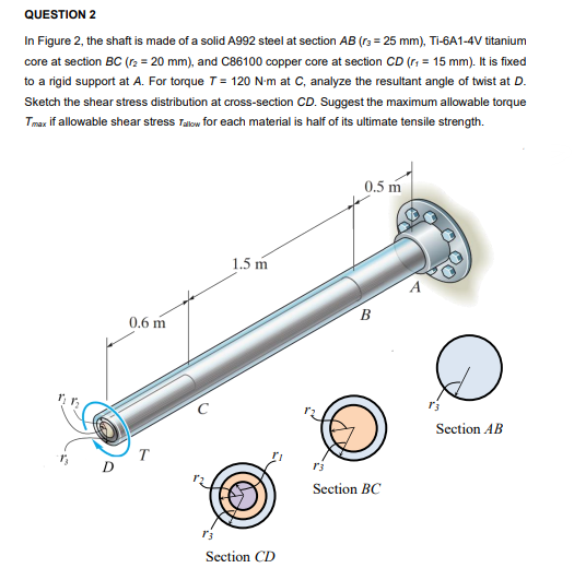
QUESTION 2 In Figure 2, the shaft is made of a solid A992 steel at section AB (rs = 25 mm), Ti-6A1-4V titanium core at section BC (r2 = 20 mm), and C86100 copper core at section CD (r; = 15 mm). It is fixed to a rigid support at A. For torque T= 120 N-m at C, analyze the resultant angle of twist at D. Sketch the shear stress distribution at cross-section CD. Suggest the maximum allowable torque Tmaz if allowable shear stress Takow for each material is half of its ultimate tensile strength. 0.5 m 1.5 m B 0.6 m Section AB T D Section BC Section CD 00
QUESTION 2 In Figure 2, the shaft is made of a solid A992 steel at section AB (rs = 25 mm), Ti-6A1-4V titanium core at section BC (r2 = 20 mm), and C86100 copper core at section CD (r; = 15 mm). It is fixed to a rigid support at A. For torque T= 120 N-m at C, analyze the resultant angle of twist at D. Sketch the shear stress distribution at cross-section CD. Suggest the maximum allowable torque Tmaz if allowable shear stress Takow for each material is half of its ultimate tensile strength. 0.5 m 1.5 m B 0.6 m Section AB T D Section BC Section CD 00

Mechanics of Materials (MindTap Course List)
9th Edition
ISBN:9781337093347
Author:Barry J. Goodno, James M. Gere
Publisher:Barry J. Goodno, James M. Gere
Chapter3: Torsion
Section: Chapter Questions
Problem 3.11.13P: A thin-walled rectangular tube has uniform thickness t and dimensions a x b to the median line of...

Related questions

Question
show me calculation for solve this question.. not like a link ..hahaha
Transcribed Image Text:QUESTION 2
In Figure 2, the shaft is made of a solid A992 steel at section AB (rs = 25 mm), Ti-6A1-4V titanium
core at section BC (r2 = 20 mm), and C86100 copper core at section CD (r; = 15 mm). It is fixed
to a rigid support at A. For torque 7 = 120 N-m at C, analyze the resultant angle of twist at D.
Sketch the shear stress distribution at cross-section CD. Suggest the maximum allowable torque
Tmaz if allowable shear stress Takow for each material is half of its ultimate tensile strength.
0.5 m
1.5 m
B
0.6 m
Section AB
T
D
Section BC
Section CD
00
Expert Solution
This question has been solved!
Explore an expertly crafted, step-by-step solution for a thorough understanding of key concepts.

Step by step
Solved in 7 steps with 7 images

Knowledge Booster


Learn more about
Need a deep-dive on the concept behind this application? Look no further. Learn more about this topic, mechanical-engineering and related others by exploring similar questions and additional content below.Recommended textbooks for you
Mechanics of Materials (MindTap Course List)
Mechanical Engineering
ISBN:
9781337093347
Author:
Barry J. Goodno, James M. Gere
Publisher:
Cengage Learning
Mechanics of Materials (MindTap Course List)
Mechanical Engineering
ISBN:
9781337093347
Author:
Barry J. Goodno, James M. Gere
Publisher:
Cengage Learning