QUESTION 3 
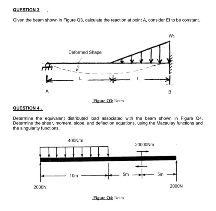
Given the beam shown in Figure Q3, calculate the reaction at point A, consider El to be constant. Wo Deformed Shape B Figure Q3: Beam
Q: Draw the F.B.D. for the beam shown in fig * and then find the reactions at A and C
A:
Q: Problem 3: For the beam shown in Figure 3. A. Find the reaction at support B (RB) B. Find the…
A:
Q: Figure 2 shows a beam subjected to distibuted loading. Knowing the beam is fixed supported at one…
A:
Q: Determine the support reactions for the beam on the left if w=150N/m and L=4m Don’t skip steps,…
A: A uniformly distributed load (UDL) is a load that is evenly distributed throughout the whole…
Q: alculate the reactions at point A for the beams shown. (Clockwise rotation of a moment - Negative,…
A: Total weight of the udl = 1(14+10)=24K it acts 12' from the A supports Using the conditions of…
Q: 4 kN A 30 6 m -2 m
A:
Q: A uniformly distributed load of (20kN/m) acts on a simply supported beam of length 4m. what are the…
A:
Q: 2. Calculate the reaction at A and B for the beam loaded as shown in Figure 2 400 lb/ft B 12'- 6'…
A:
Q: 5. Determine the reactions for the beam with both concentrated and distributed loads, as shown in…
A:
Q: Consider the element shown in Figure 3. Assume that F is given and that M= F x 1 [Nm]. a) Compute…
A: (a) The free-body diagram of the beam is given as, Apply the force equilibrium in the horizontal…
Q: Determine the reactions at A and B for the loaded beam as shown in Figure
A:
Q: For the beam shown in Figure 1. A. Find the reaction at support A (RA) B. Find the reaction at…
A:
Q: For the beam shown in Figure 3. A. Find the reaction at support B (Rg) B. Find the reaction at…
A: Draw the free-body diagram of the beam.
Q: 6. The upper beam in Figure 1-64 is supported at D and a roller at C which separates the upper and…
A: Find the reactions at point A,B,C and D.
Q: Given: The beam shown below is cantilevered at the left end, with forces applied as shown.…
A: It required to Draw FBD of cantilever beam subjected to given load Find reactions at fixed support…
Q: Q.2/The rigid beam shown in Figure 2 is supported by a pin at A and wires BD a
A:
Q: Determine the reactions at A and B for the beams loaded as shown in Figure 10. Beam weight may be…
A: To Find : The reaction at point A and B. FBD: The free body diagram of beam:
Q: For the beams loaded as shown in the figure, determine the following A Determine the reactions at…
A:
Q: or the statically indeterminate beam shown in Figure 3, EI is constant. Assume 1, 2, and 3 are…
A:
Q: Find the support reactions A and B at static equilibrium for the loaded beam shown below in fig 4.1
A:
Q: USE IMAGE BELOW Question; Draw and fully label the Freebody diagram of the BEAM in the picture…
A:
Q: Figure below shows a simply supported uniform beam supports a 40 kN load. Determine the reactions R.…
A: for solution refer below images.
Q: (iii) Determine the support reactions for the following loaded beam as shown in Figure 3.
A: Convert the uniformly distributed load into point load, P=20 kN/m×6 m=120 kN Convert the uniformly…
Q: Question 2 A propped cantlever beam in Figure Q2 is loaded by a triangularly distrnbuted load of…
A: (2.1)For equilibrium conditions, determine the directions of reactions at points A (RA) and B (RB)…
Q: modulus E of elasticity, for the ACB beam with inertia I; a) find the elastic curve equation by the…
A:
Q: Problem 2: Determine the support reactions for The beam shown below /2 2N/m 600 N 4N/M 200 N 45 02 m…
A:
Q: 50kN 10kN/m 3m 4m 6m Qr Calculate the reactions at A and B for the beam shown in (Fig(r).
A: Given data: Magnitude of point load, P=50 kN
Q: iven beams. Indicate its directio
A:
Q: USE IMAGE BELOW Question; draw and fully label the Freebody diagram of the BEAM in the picture…
A:
Q: For the simply supported beam shown below find reactions at supports A a В. 2m 14KN 3m 28KN 2m B. D.
A: Let us draw the free body diagram Using the conditions of equilibrium ∑Fy=0RB+RD-14-28=0RB+RD=42KN
Q: Draw the F.B.D. for the beam shown in fig * ? and then find the reactions at A and C
A:
Q: (a) Calculate reactions at A and B in beam shown in Figure Q17
A: Given data: Point load = P = 1000 N Length AB = 9 m Moment = M = 2100 N-m.
Q: Question 4 Derive the equations of the deflection curve for a simple beam AB loaded by a couple (4…
A: Write the bending moment equation.
Q: Problem 2: For the beam shown in Figure A. Find the reaction at support B (RB) B. Find the reaction…
A: Given Data
Q: (iii) Determine the support reactions for the following loaded beam as shown in Figure 3. 15 kN…
A:
Q: Consider the beam shown in (Figure 1). Suppose that w = 880 N/m . Determine the y component of…
A: Apply moment equilibrium at B.
Q: Question 4 A beam made up of two unequal leg angles is subjected to a bending moment M having vector…
A: Calculate the center position.
Q: Compute the moment of area of the M diagram between the reactions about both the left and the right…
A:
Q: A В L
A: given; AB=Lweight density=qlets take reaction force at A=RA
Q: 1. Determine the reactions at A and B for the beams loaded as shown in Figure (a)-(c) below. Beam…
A: For the given beam Assumption Weight of beam is neglected To determine Reactions at A and B
Q: Problem 3: For the beam shown in Figure A. Find the reaction at support B (RB) B. Find the reaction…
A:
Q: 3. Determine the reaction force at A and B for the beam shown in Figure. - 4 - 60) kN/m om
A: Let Ra and Rb are reactions at A and B We will use integration method to solve this…
Q: 4- The value of reaction acting on point B, for the simply supported beam shown in Figure (1) below…
A: Solution:
Q: 2- For the beam shown below The moment of inertia = / and the elastic modulus E a) Find the reaction…
A:
Q: calculate the reactions. (b) How many runs of analysis are required to compute the internal forces?…
A:
Q: Q3- Determine the reactions for the beam loaded as shown in the figure. 150Nlm
A:
Q: C b
A:
Q: en, draw SFD and BMD using semi graphical method.
A:
Q: For a 200 mm x 200 mm beam shown below with E = 20 GPa, select in the %3D choices the value that…
A:
Trending now
This is a popular solution!
Step by step
Solved in 2 steps with 2 images
- A cantilever beam of a length L = 2.5 ft has a rectangular cross section {b = 4in,, h = Sin,) and modulus E = 10,000 ksi. The beam is subjected to a linearly varying distributed load with a peak intensity qQ= 900 lb/ft. Use the method of superposition and Cases 1 and 9 in Table H-l to calculate the deflection and rotation at B.A fixed-end beam AB carries point load P acting at point C. The beam has a rectangular cross section (b = 75 mm, h = 150 mm). Calculate the reactions of the beam and the displacement at point C. Assume that E = 190 GPa.A cantilever beam model is often used to represent micro-clectrical-mechanical systems (MEMS) (sec figure}. The cantilever beam is made of polysilicon (E = 150 GPa) and is subjected to an electrostatic moment M applied at the end of the cantilever beam. 1 f dimensions arc h — 2 [im, h — 4 ^m, and L = 520 ^mt find expressions for the tip deflection and rotation of the cantilever beam in terms of moment M.
- -6 Calculate the maximum deflection of a uniformly loaded simple beam if the span length L = 2.0 m, the intensity of the uniform load q = 2.0 kN/m, and the maximum bending stress = 60 MPa, The cross section of the beam is square, and the material is aluminum having modulus of elasticity E = 70 GPa. (Use the formulas of Example 9-1.)-22 Derive the equations of the deflection curve for a simple beam AB with a distributed load of peak intensity q0acting over the left-hand half of the span (see figure). Also, determine the deflection cat the midpoint of the beam. Use the second-order differential equation of the deflection curve.Beam ABC is loaded by a uniform load q and point load P at joint C. Using the method of superposition, calculate the deflection at joint C. Assume that L = 4 m, a =2ra, q = 15 kN/m, P = 7.5 kN, £ = 200 GPa, and / = 70.8 X 106 mm4.
- A propped cantilever steel beam is constructed from a W12 × 35 section. The beam is loaded by its self-weight with intensity q. The length of the beam is 1L5 ft. Let E = 30,000 ksi. Calculate the reactions at joints A and B. Find the location of zero moment within span AB. Calculate the maximum deflection of the beam and the rotation at joint B.A fixed-end beam AB of a length L is subjected to a uniform load of intensity q acting over the middle region of the beam (sec figure). Obtain a formula for the fixed-end moments MAand MBin terms of the load q, the length L, and the length h of the loaded part of the beam. Plot a graph of the fixed-end moment MAversus the length b of the loaded part of the beam. For convenience, plot the graph in the following nondimensional form: MAqL2/l2versusbL with the ratio b/L varying between its extreme values of 0 and 1. (c) For the special case in which ù = h = L/3, draw the shear-force and bending-moment diagrams for the beam, labeling all critical ordinates.-4 A simple beam ABCD has moment of inertia I near the supports and moment of iertia 2I in the middle region, as shown in the figure. A uniform load of intensity q acts over the entire length of the beam. Determine the quations of the deflection curve for the left-hand half of the beam. Also, find the angle of rotation A at the left-hand support and the deflection max at the midpoint.
- Copper beam AB has circular cross section with a radius of 0.25 in. and length L = 3 ft. The beam is subjected to a uniformly distributed load w = 3.5 lb/ft. Calculate the required load P at joint B so that the total deflection at joint B is zero. Assume that£ = 16,000 ksi.Obtain a formula for the ratio c/maxof the deflection at the midpoint to the maximum deflection for a simple beam supporting a concentrated load P (see figure). From the formula, plot a graph of c/max versus the ratio a/L that defines the position of the load (0.5 < a/L < ) What conclusion do you draw from the graph? (Use the formulas of Example 9-3.)A counterclockwise moment M0acts at the midpoint of a fixed-end beam ACB of length L (see figure). Beginning with the second-order differential equation of the deflection curve (the bendingmoment equation), determine all reactions of the beam and obtain the equation of the deflection curve for the left-hand half of the beam. Then construct the shear-force and bending-moment diagrams for the entire beam, labeling all critical ordinales. Also, draw the deflection curve for the entire beam.