Question 4 4. (a) Construct a Thévenin equivalent circuit across the terminals a, b for the circuit shown in Figure 4.1. 25 N a 8 V 1 A 30 Ω Figure 4.1
Question 4 4. (a) Construct a Thévenin equivalent circuit across the terminals a, b for the circuit shown in Figure 4.1. 25 N a 8 V 1 A 30 Ω Figure 4.1

Introductory Circuit Analysis (13th Edition)
13th Edition
ISBN:9780133923605
Author:Robert L. Boylestad
Publisher:Robert L. Boylestad
Chapter1: Introduction
Section: Chapter Questions
Problem 1P: Visit your local library (at school or home) and describe the extent to which it provides literature...

Related questions
Question
Transcribed Image Text:Question 4
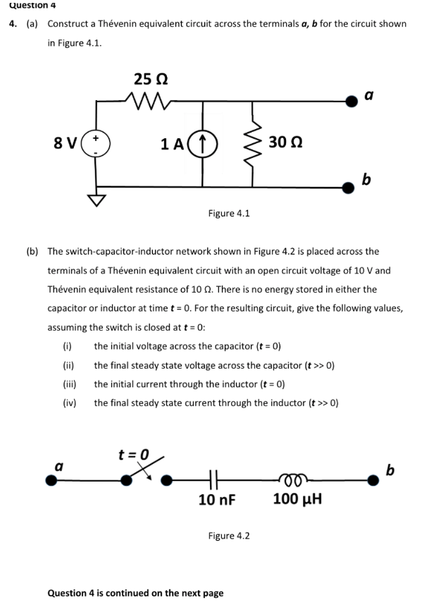
4. (a) Construct a Thévenin equivalent circuit across the terminals a, b for the circuit shown
in Figure 4.1.
25 N
a
8 V
1 A
30 Ω
b
Figure 4.1
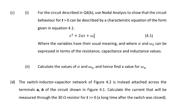
(b) The switch-capacitor-inductor network shown in Figure 4.2 is placed across the
terminals of a Thévenin equivalent circuit with an open circuit voltage of 10 V and
Thévenin equivalent resistance of 10 0. There is no energy stored in either the
capacitor or inductor at time t = 0. For the resulting circuit, give the following values,
assuming the switch is closed at t = 0:
(i)
the initial voltage across the capacitor (t = 0)
(ii)
the final steady state voltage across the capacitor (t >> 0)
(ii)
the initial current through the inductor (t = 0)
(iv)
the final steady state current through the inductor (t >> 0)
t = 0
a
b
10 nF
100 µH
Figure 4.2
Question 4 is continued on the next page
Transcribed Image Text:(c)
(i)
For the circuit described in Q4(b), use Nodal Analysis to show that the circuit
behaviour for t>0 can be described by a characteristic equation of the form
given in equation 4.1.
s2 + 2as + wž
(4.1)
Where the variables have their usual meaning, and where a and wo can be
expressed in terms of the resistance, capacitance and inductance values.
(ii)
Calculate the values of a and wo, and hence find a value for wa
(d) The switch-inductor-capacitor network of Figure 4.2 is instead attached across the
terminals a, b of the circuit shown in Figure 4.1. Calculate the current that will be
measured through the 30 Q resistor for t>>0 (a long time after the switch was closed).
Expert Solution
This question has been solved!
Explore an expertly crafted, step-by-step solution for a thorough understanding of key concepts.

Step by step
Solved in 2 steps with 4 images

Knowledge Booster


Learn more about
Need a deep-dive on the concept behind this application? Look no further. Learn more about this topic, electrical-engineering and related others by exploring similar questions and additional content below.Recommended textbooks for you
Introductory Circuit Analysis (13th Edition)
Electrical Engineering
ISBN:
9780133923605
Author:
Robert L. Boylestad
Publisher:
PEARSON

Delmar's Standard Textbook Of Electricity
Electrical Engineering
ISBN:
9781337900348
Author:
Stephen L. Herman
Publisher:
Cengage Learning

Programmable Logic Controllers
Electrical Engineering
ISBN:
9780073373843
Author:
Frank D. Petruzella
Publisher:
McGraw-Hill Education
Introductory Circuit Analysis (13th Edition)
Electrical Engineering
ISBN:
9780133923605
Author:
Robert L. Boylestad
Publisher:
PEARSON
Delmar's Standard Textbook Of Electricity
Electrical Engineering
ISBN:
9781337900348
Author:
Stephen L. Herman
Publisher:
Cengage Learning
Programmable Logic Controllers
Electrical Engineering
ISBN:
9780073373843
Author:
Frank D. Petruzella
Publisher:
McGraw-Hill Education

Fundamentals of Electric Circuits
Electrical Engineering
ISBN:
9780078028229
Author:
Charles K Alexander, Matthew Sadiku
Publisher:
McGraw-Hill Education

Electric Circuits. (11th Edition)
Electrical Engineering
ISBN:
9780134746968
Author:
James W. Nilsson, Susan Riedel
Publisher:
PEARSON

Engineering Electromagnetics
Electrical Engineering
ISBN:
9780078028151
Author:
Hayt, William H. (william Hart), Jr, BUCK, John A.
Publisher:
Mcgraw-hill Education,