QUESTION 4 
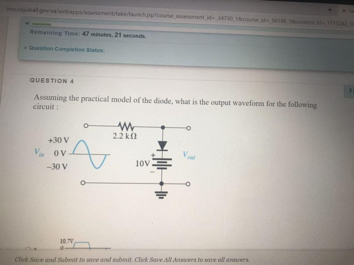
Assuming the practical model of the diode, what is the output waveform for the following circuit : 2.2 k2 +30 V Vin OV out -30 V 10V
Q: Q1. Determine the forward voltage and forward current for the diode in Figure (1) for each of diode…
A:
Q: 330 R V Si D1 ASi D2 9V
A:
Q: V1 R1 10V D1 Vc 1kHz 2.5k2 0° 3
A: Negative shunt clipper is given in the . & we have to find the output.
Q: What is the value of current flowing through the diode? 4 Q + 4.7 V
A: Considering the diode is ideal diode . Diode voltage Vd= 0v (short circuit) Then Calculate current…
Q: D1 R ww S本
A: The peak inverse voltage or PIV is the maximum voltage that is tolerated by the diode in the reverse…
Q: What is the diode's power dissipation if the diode voltage is 1.1 V and the diode current is 2 A? O…
A:
Q: 2. Determine the diode is contacting or not. 100 V,12 v V a 10V
A:
Q: QUESTION 6 Determine whether each silicon diode in the following figure is forward biased (fb) or…
A: To determine the voltage across the diode by using practical model. As the both the terminal of…
Q: 1.25 Assuming the diodes to be ideal in the figure, for the output to be clipped, the input voltage…
A: When , 2V > VAB > -1V Then D1 and D2 will be ON and Vo = – 2 volt. For D1 to be OFF, VAB <…
Q: Determine the reverse voltage and reverse current for the diode in Figure 2 below for each of the…
A: We need to find out current and voltage for given circuit for different case .
Q: 50 2 ww R1 A V = 10 V=
A: Given that circuit
Q: 2.14 What is the peak forward current (i,e. IF through each diode in 2.11? +5 V +50 V | Vin Vin R 47…
A: Peak forward current through diode?
Q: V1 D1 R1 R2 1ka 2k0 10 V Figure 3.
A:
Q: 2. Determine the diode is contacting or not. 10 2 ww V,12 V- Three V, 10 V 3. Find the values of I…
A: In this question we will find that diode is conducting or not...
Q: Determine if the diode is forward or reverse biased. Solve for V1 and V2. + 10V 2 k2 4 kn 8 ka 6 kn
A: The solution is given below
Q: For the given circuit, assuming an ideal diode, the value of current I will be: +5 V $2.540 O a 0 mA…
A: Given circuit,
Q: 2. Determine the diode is contacting or not. 512 10 S2 ww ww 1=12 V- V, 10 V
A: Given circuit:
Q: 6. Plot v, for each circuit in figure.3 for the input shown. Assume the barrier potential of diode…
A:
Q: What is the value of current flowing through the diode? 4 Ω + 4.7 V 7Ω.
A:
Q: CHOICES: Oa. Ob. QUESTION #4. Assuming ideal diodes, select from the choices shown the output…
A: As given diode is ideal. Forward voltage drop of ideal diode is 0V i.e. act as short circuit.…
Q: What is the value of reverse recovery charge developed in diode having the rate of fall of diode…
A: Find the recovery charge if the fall rate of diode current and recovery time is given.
Q: Determine the voltage across R2 for the first and second diode approximations. Diode: Si, r = 10 N,…
A:
Q: 4- A certain voltage doubler has 20 V rms on its input. What is the output voltage? Draw the…
A: We need to draw the voltage doubler circuit .
Q: 4) Determine vo and the required PIV rating of each diode for the configuration in the following…
A: Find V0 when supply voltage is positive and negative both
Q: Hw2: Find the current flowing in the circuit of figure 3 if the diode can be described by: (a) the…
A: By ohms law current in a resistor = voltage across resistor / resistance. We will apply KVL in loop…
Q: CHOICES: Oa. Ob. QUESTION #4. Assuming ideal diodes, select from the choices shown the output…
A:
Q: 36 - In the Zener diode regulated circuit, the input voltage value of the regulated circuit should…
A: To find out the correct answer
Q: Assuming the practical model of the diode, what is the output waveform for the circuit shown below.…
A:
Q: What is the diode's power dissipation if the diode voltage is 1.1 V and the diode current is 2 A? O…
A: Given Diode voltage drop VD = 1.1 V diode current iD = 2A
Q: 100nF Input Voltage AC Voltage 1MQ 5 сарacitor 5V diode 1N4001 -5 3V
A:
Q: 4. Find Vo, I, Io1, and loz. Use practical diode mod Vin= 10 V R1 = 0.33 ΚΩ V₂
A: Given : RI=0.33 kΩVIN=10 V Find: ID1ID2IV0
Q: 1. Draw the output voltage waveform for each circuit and include the voltage values. +5 V +50 V Vin…
A: 1) Given circuit (a), Input waveform is
Q: Q4: (a) Determine the peak value of the output voltage for Figure 1 if n= 2 and Vp(in) = 312 V. (b)…
A:
Q: What is the value of reverse recovery charge developed in diode having the rate of fall of diode…
A: Find the reverse recovery charge of the diode. If the rate of fall of diode is given and recovery…
Q: A string of three diode is used to provide a constant voltage of about 2.1 V. Assume n = 2 and…
A: a With no load i.e. RL=0ΩThen value of current in the diode stringI=10-2.11=7.9mAThus each diod will…
Q: 100 V 10Ω 5 V 560 N 8 V (a) (b)
A: Silicon diode have forward voltage drop is 0.7V.
Q: The ezener diode shown in the circuit below will be conducting if the load voltage equals to |ト52 Vz…
A:
Q: A Si diode has a leakage current IS = 71 nA at room temperature (25°). The leakage current if the…
A: The solution is given below
Q: in +20V V in 500 2 out -20V Figure 1. Circuit for Question 1 and 2. 2. Sketch the output waveform if…
A:
Q: Draw the output voltage waveform. 100 V "Ideal diodes -100 v 2.2 k2 22 k2 2.2 k
A:
Q: The diodes in the circuit are all Silicon with forward voltage of 0.7 V. If R1 = 14N and R2 = 140,…
A: Given circuit
Q: What is the value of current flowing through the silicon diode? 4 2 12 4.7 V 7Ω 1Ω
A: Given circuit,
Q: 2. Determine the diode is contacting or not. 5 S2 Ww 10 A ww Vw = 10 V V, = 12 V-
A:
Q: 1) The color of this resistor 47 k52 A yellow, violet,orange. b) yellow, violet, red c) yellow,blue,…
A:
Q: If D1, D2 and D3 are removed in the circuit and are replaced by short circuit, determine the PIV…
A:
Q: What is the most suitable value of resistor R for this diode circuit? * 9V o R Si Si Si 5V, 50mA
A: In this question we need to find a value of resistance R for the diode circuit.
Q: What is the diode's power dissipation if the diode voltage is 0.7 V and the diode current is 0.5 A?…
A: The diode problem, the solution is given below
Q: What is the value of reverse recovery charge developed in diode having the rate of fall of diode…
A: Reverse recovery charge=12×Peak value of reverse current×reverse recovery time.
Q: D1 2 4 2V R1 V1 2.5k2 10V 1kHz 3 0° +
A:
Q: 5. Assume each diode in the circuit has a cut in voltage of 0.65V. The input voltage is Vi = 5V.…
A:
Step by step
Solved in 5 steps with 6 images
- What is CEMF?A 1N4738A zener diode has a ZZ of 4.5 Ω. Taking the data from the datasheet we have VZ = 8.2 V with a test current, IZ, of 31 mA. What is the voltage across the zener terminals when the current is 15 mA? When the current is 55 mA? Make the representation of the values by means of their curve characteristic.Determine the noise current for a diode with a forward bias of 1mA over a 100 kHz bandwidth. If the diode is in a circuit with 500Ω series resistance, calculate the total output noise voltage at 27°c. (from miller: In = 0.00566µA, total noise voltage = 0.154 µVrms)
- A diode is doped with NA = 1018/cm3 on the p-type side and ND =1019/cm3 on the n-type side. (a)What is the depletion-layer width wdo? (b) What are the values of xp and xn? (c) What is the value of the built-inpotential of the junction?(d) What is the value of EMAX? Use Eq. E(x) = 1 /εs ∫ ρc(x) dxand as shown.Suppose we have a 10-Hz sinusoidal voltage source, vin(t). Draw the diagram of a circuit that clamps the positive peaks to -4 V. The circuit should be composed of ideal diodes, dc voltage sources, and other components as needed. List any constraints that should be observed in selecting component values. Be sure to label the terminals across which the clamped output waveform vo(t) appears.Create the Diode Characteristic Curve for this data values. Diode Voltage (VD) Diode Current (ID) 0.890904 9.109 0.884515 7.115 0.876023 5.124 0.86333 3.137 0.837654 1.162 0.793023 0.206975 0.779114 0.120885 0.754079 0.04592 0.695273 0.004727 0.599882 0.000118256 0.499998 0.000002487 0.4 5.2464E-08 0.3 1.39E-09 0.2 2.23008E-10 0.1 1.00568E-10 0 0 -0.1 -1.0011E-09 -0.2 -2.00211E-09 -0.3 -3.0031E-09 -0.4 -4.00411E-09 -0.5 -5.0051E-09 -0.6 -6.0061E-09 -0.7 -7.0071E-09 -0.8 -8.0081E-09 -0.9 -9.00911E-09 -1 -1.001E-08 -2 -2.002E-08 -4 -4.004E-08 -6 -6.006E-08 -8 -8.008E-08 -10 -1.001E-07 -20 -2.002E-07 -40 -4.004E-07 -60 -6.006E-07 -80 -8.008E-07 -100 -0.000001001 -200 -0.000002002 -300 -0.000003003 -400 -0.000004004 -500 -0.000005005
- The output of a diode used as a solar cell is given by IC =1−10−15[exp(40VC)−1] amperes What operating point corresponds to Pmax? What is Pmax? What are the values of ISC and VOC?Subject : Electronics Engineering A crystal diode having an internal resistance ri=10Ω is used for center tapped full wave rectification. If the applied voltage is V=50 sin(πt) and the load resistance is RL= 1KΩ, determine the followingsi) Draw the input and output voltage and current waveformsii) The efficiency of the circuit.iii) The ripple factor.Consider the diode circuit shown and by assuming Vγ = 0.6 V and rf = 20 Ω; i. determine the diode voltage VD and output voltage Vo. ii. If the diode connection is reversed (i.e., the diode is in up-side down direction), compute the new diode voltage VD and output voltage Vo.
- The voltage drop of schottky diode is more than that of power diode? true or fales1. The applied voltage in a Germanium diode is found to be 0.41 V with a threshold voltage of 26 mV and saturation current of 1 nA Calculate for the diode current. 2.The voltage as the switch is closed for an SCR circuit is found to be 4V and the current is 0.2A Compute for the average power conduction loss for a frequency of 60 H2 Assume the tum on and turn off time is 0.12 m and 0.25 ms respectively 3.If the trigger voltage in the circuit is replaced by SV, the series resistor by 330 ohms, compute for the gate current at the SCR when Switch 1 and 2 are momentarily switched on. The voltage at the gate to cathode is 0.7V while that of the voltage from anode to cathode is 10V 4.Id=11.84 mA n=2, and the applied bias voltage is 0.5V and the temperature requirement is at 20°C. Findthe diode saturation current 5.For a frequency of 60 Hz, compute for the average power conduction loss if the difference in the turn off and turn on time is 10 ms and the instantaneon power is given as a…Considering a clamper circuit, where capacitance C, load R, the cut-in voltage of diode are unknown, which is the correct statement 1- the dc level of the signal changes 2- the peak-to-peak value of signal changes 3- the shape of signal changes 4- the dc level shifts up 5- the dc level shifts down