Question 4: I. Suppose that we have a memory chip as shown below and we want to create a 32x16 module: 4 bits a. What will be the number of chips that should be used to design this module? Show your calculation steps. b. What will be the last address number in this new module? c. Draw the diagrarn of the desired module and show the address number of each row. II. Based on what you have learned in chapter 3about the combinational circuits and in chapter 4 about the MARIE ISA, connect the below diagram components in the proper way such that each of the given five instructions below will be enabled according to the applied values at the opcode bits (The address part is not involved in this diagram). For example, if the input bits are 0000 then JNS gate should be enabled. N.B: Only one gate should be enabled at a time, based on the applied input. Opcode Operand Load Add Input Skipcond Jumpl
Question 4: I. Suppose that we have a memory chip as shown below and we want to create a 32x16 module: 4 bits a. What will be the number of chips that should be used to design this module? Show your calculation steps. b. What will be the last address number in this new module? c. Draw the diagrarn of the desired module and show the address number of each row. II. Based on what you have learned in chapter 3about the combinational circuits and in chapter 4 about the MARIE ISA, connect the below diagram components in the proper way such that each of the given five instructions below will be enabled according to the applied values at the opcode bits (The address part is not involved in this diagram). For example, if the input bits are 0000 then JNS gate should be enabled. N.B: Only one gate should be enabled at a time, based on the applied input. Opcode Operand Load Add Input Skipcond Jumpl

Chapter4: Processor Technology And Architecture
Section: Chapter Questions
Problem 4PE

Related questions

Question
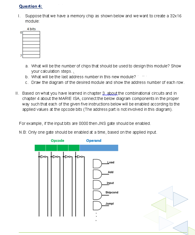
Transcribed Image Text:Question 4:
I. Suppose that we have a memory chip as shown below and we want to create a 32x16
module:
4 bits
a. What will be the number of chips that should be used to design this module? Show
your calculation steps.,
b. What will be the last address number in this new module?
c. Draw the diagram of the desired module and show the address number of each row.
II. Based on what you have learned in chapter 3 abaut the combinational circuits and in
chapter 4 about the MARIE ISA, connect the below diagram components in the proper
way such that each of the given five instructions below will be enabled according to the
applied values at the opcode bits (The address part is not involved in this diagram).
For example, if the input bits are 0000 then JNS gate should be enabled.
N.B: Only one gate should be enabled at a time, based on the applied input.
Opcode
Operand
Load
Add
Input
Skipcond
Jumpl
Expert Solution
This question has been solved!
Explore an expertly crafted, step-by-step solution for a thorough understanding of key concepts.

Step by step
Solved in 2 steps with 2 images

Knowledge Booster


Learn more about
Need a deep-dive on the concept behind this application? Look no further. Learn more about this topic, computer-science and related others by exploring similar questions and additional content below.Recommended textbooks for you
Systems Architecture
Computer Science
ISBN:
9781305080195
Author:
Stephen D. Burd
Publisher:
Cengage Learning
Systems Architecture
Computer Science
ISBN:
9781305080195
Author:
Stephen D. Burd
Publisher:
Cengage Learning