Questions: - 1. For the circuit of Figure (1), the voltage gain from base to collector is approximately: (a)l (b)12 (c)112 (d)224 2. The output signal of the common-emitter amplifier is out-of-phase with the input by: (a)0° (b)45° (c)90° (d) 180° 3. If the emitter bypass capacitor in Figure (1) is removed, the Amplifier voltage gain will: (a) Increase. (b) Decrease. (c) Remain essentially the same. 70 4. If the emitter bypasses capacitor in Figure (1) is shoricu, the voltage gain will increase. (a). The voltage gain will remain the same. (c) The transistor will saturate. (d) None of the above. 5. If the load resistor RL in the circuit of Figure (1) is made larger, the amplifier voltage gain will (a) Increase. (b) Decrease. (c) Remain essentially the same. main 欧 1.13 Ucc = 10 v G|1=1 kHr B Rpart 1 130 A Ran 2 Un 100 ( 5 1 pF Up 30 mV R₁ 1945 Fig.1 1X0 R₂ 470 (1 V₁bps Type 91182 V₁ R₂ 100 Cz 0.22 F to point Ucul Y₂ Y₁ M
Questions: - 1. For the circuit of Figure (1), the voltage gain from base to collector is approximately: (a)l (b)12 (c)112 (d)224 2. The output signal of the common-emitter amplifier is out-of-phase with the input by: (a)0° (b)45° (c)90° (d) 180° 3. If the emitter bypass capacitor in Figure (1) is removed, the Amplifier voltage gain will: (a) Increase. (b) Decrease. (c) Remain essentially the same. 70 4. If the emitter bypasses capacitor in Figure (1) is shoricu, the voltage gain will increase. (a). The voltage gain will remain the same. (c) The transistor will saturate. (d) None of the above. 5. If the load resistor RL in the circuit of Figure (1) is made larger, the amplifier voltage gain will (a) Increase. (b) Decrease. (c) Remain essentially the same. main 欧 1.13 Ucc = 10 v G|1=1 kHr B Rpart 1 130 A Ran 2 Un 100 ( 5 1 pF Up 30 mV R₁ 1945 Fig.1 1X0 R₂ 470 (1 V₁bps Type 91182 V₁ R₂ 100 Cz 0.22 F to point Ucul Y₂ Y₁ M

Chapter25: Television, Telephone, And Low-voltage Signal Systems
Section25.1: Television Circuit
Problem 5R: From a cost standpoint, which system is more economical to install: a master amplifier distribution...

Related questions

Question
Transcribed Image Text:Questions: -
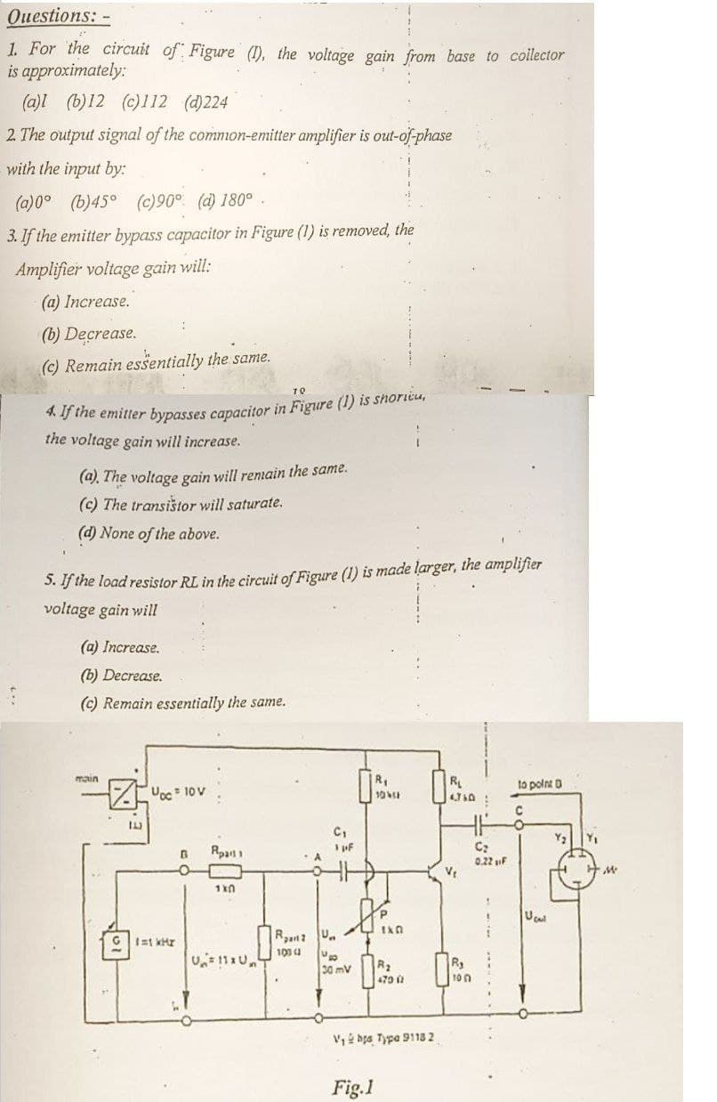
1. For the circuit of Figure (1), the voltage gain from base to collector
approximately:
is
:
(a)l (b)12 (c)112 (d)224
2. The output signal of the common-emitter amplifier is out-of-phase
with the input by:
(a)0° (b)45° (c)90° (d) 180°.
3. If the emitter bypass capacitor in Figure (1) is removed, the
Amplifier voltage gain will:
(a) Increase.
(b) Decrease.
(c) Remain essentially the same.
70
4. If the emitter bypasses capacitor in Figure (1) is shoricu,
the voltage gain will increase.
(a). The voltage gain will remain the same.
(c) The transistor will saturate.
(d) None of the above.
5. If the load resistor RL in the circuit of Figure (1) is made larger, the amplifier
voltage gain will
(a) Increase.
(b) Decrease.
(c) Remain essentially the same.
main
Đọc To
1.1.3
G 1=1 kHr
R₁
104
H.H
C₁
1 pF
C₂
0.22 F
V₁
THE
R2 U
100 ( U
30 mV
R₂
470 (1
B Rpart 1
1x0
V₁ bts Type 91182
Fig.1
R₁
4.760:
10
to point D
C
Ucu
Y₁
M
Expert Solution
This question has been solved!
Explore an expertly crafted, step-by-step solution for a thorough understanding of key concepts.

Step by step
Solved in 2 steps

Knowledge Booster


Learn more about
Need a deep-dive on the concept behind this application? Look no further. Learn more about this topic, electrical-engineering and related others by exploring similar questions and additional content below.Recommended textbooks for you
EBK ELECTRICAL WIRING RESIDENTIAL
Electrical Engineering
ISBN:
9781337516549
Author:
Simmons
Publisher:
CENGAGE LEARNING - CONSIGNMENT
EBK ELECTRICAL WIRING RESIDENTIAL
Electrical Engineering
ISBN:
9781337516549
Author:
Simmons
Publisher:
CENGAGE LEARNING - CONSIGNMENT