B R m R m R R 
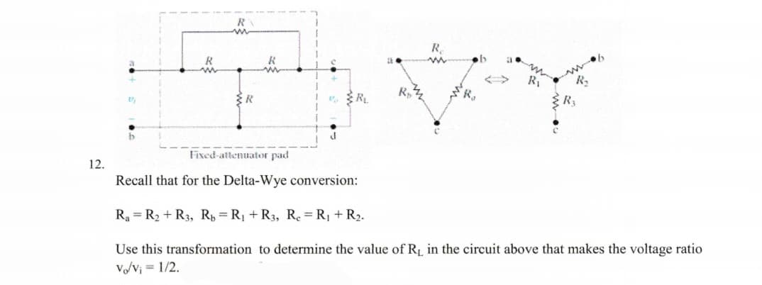
Fixed-attenuator pad R₁
Q: Find the solution to the following system of equations. w" +y" = t², w" - y" = 4t; y(0) = y'(0) = w'…
A:
Q: Boolean Algebra
A: As per company rule, an expert can give solution for one question with its subparts, here 2…
Q: 2+j3 1 + 8/90° 6 Report your answer so that all angles are in the range of 0 degrees to positive 180…
A: The polar form and rectangular form is shown in next step.
Q: 100 s5+254 +45³+ 5s²+s+2 complete the routh table for the function- Determine whether the response…
A: The stability of the system can be computed by using the Routh Hurwitz criterion and based on the…
Q: (6) The circuits below are in steady state. (a) Find the complex power received by the capacitor, in…
A: Given data Resistance, R=2Ω Capacitance, C=10 mF Supply current, is=5cos100t+π3 A A voltmeter is…
Q: 4. A modulating signal m(t) = 10 cos 210³t is amplitude modulated with a carrier signal c(t) = 50…
A: Given data: A modulating signal, m(t)=10cos2π103t A carrier signal, ct=50cos2π105t
Q: ries AC circuit is composed of a 75 Ohms resistor, 25 mH inductor and a 0.02 μF capacitor. The…
A:
Q: 1. For each signal below, determine the largest sampling interval T, such that aliasing does not…
A: Signal A signal is the fundamental quantity used in electrical engineering to represent some…
Q: For a given 2nd order system determine: a. Response; b. Damping ration; c. Natural frequency 25…
A:
Q: 6600/440 V single-phase 600 kVA transformer has 1200 primary turns. What is the voltage per turn of…
A:
Q: For a unity feedback system with G(s) = K s(s+5) (s+8) plot and refine the root locus by finding all…
A: Given, Unity feedback system is having G(s) = K/[s(s+5)(s+8)] We need to plot root locus by finding…
Q: Q4. Determine the Nyquist sampling rate and Nyquist interval for the following analog signals (a) 1+…
A:
Q: 6. The root mean-square(effective) voltage V. =√√√√²& 2 dt rms . Find the value of rms if where T is…
A:
Q: Draw a graph that models the connecting relationships in the floorplan below. The vertices represent…
A: The given floorplan is shown below, Here, The vertices indicate the rooms, while the edges…
Q: Equivalent capacitance across terminal AB
A: Given circuit- To find- Equivalent capacitance at terminal AB.
Q: Using a DMM you are troubleshooting a 480 volt, 3 phase power feeding a fused disconnect connected…
A: Given Unbalance current measurement I A =56 A I B =55 A I C =52 A
Q: A 75-hp, 460-V, 4-pole, 60-Hz, Y-connected induction motor develops its full-load induced torque at…
A:
Q: M(r) T₁ oann@ M-TJ MI-T₂) Figure 64-1 Baseband decoder to obtain din) from M 6.4-1. The bit stream…
A:
Q: Q2. For the message signal shown in figure below with modulation index equals to 0.8, find the…
A:
Q: Using the figues provided, if the Resister Radj is adjusted to 175 ohms, what is the rotational…
A:
Q: For the sample-and-hold circuit, determine the largest-value of capacitor that can be used…
A: Sample-And-Hold Circuit :- A typical data-acquisition system receives signals from a number of…
Q: Why resistance only consumes or draws real power? Why reactance does not?
A: The given solution is follows.
Q: Question # 1: For a unity feedback system with a forward transfer function: G(s) = K/[s(s+50)(s +…
A:
Q: QUESTION 1 1.1 Characterise two cathode processes in gas discharges. 1.2 Give a detailed explanation…
A: Power System The power system is a network that includes generation, distribution, and transmission.…
Q: Let Vab_c be the voltage when RL is connected and Vab_d when RL is disconnected, find these peak…
A:
Q: Find the right-sided signal x[n], whose z-transform is 1-az-1 z-¹-a X(z) =
A:
Q: I have a question regarding Fourier Series. I'm learning now two things: 1- Fourier Series…
A: Given data Fourier series coefficients of even and odd functions is given as well as the Fourier…
Q: In power distribution systems, what is sometimes necessary to install to reduce harmonic frequencies…
A: Cause of Harmonics and distortion in Powet system Addition of Non Linear load such as Power…
Q: Compute a Nyquist sampling rate for reconstructing the following signal from its samples: sin(40лt)…
A:
Q: Use dynamic programming method to determine the most economical units to be committed to supply a…
A:
Q: 5.46. Compute the input/output impedance and voltage gain of the stages shown in Fig. 5.138. Assume…
A: The BJT have three terminal base, emitter, and collector. It has two pn junction. It act as…
Q: 2. A full-wave bridge rectifier is operated from a 50 Hz, 220 V rms line. It has a 100 µF filter…
A: In this question We need to determine the percent ripple of the system and also determine the…
Q: 2. Describe the action of the circuit shown in figure-2 below a. Vin RE -O+Vcc SPEAKER
A: The given circuit diagram is shown below. We need to discuss the action of this circuit.
Q: (6) The circuit below is in steady state. (a) Sketch the phasor of vå (make sure the magnitude and…
A:
Q: II кл 50 мг т 24v вкл ww it 20μF + V lak The switch has been open for a long time. At t= 0 it is…
A:
Q: At 0-, no currrent flows through the capacitors because they are open, how did you combine the…
A:
Q: Calculate the losses of this transformer in W. V₁ = 229.01 V 1₁ = 0.49 A cos($1) = 1 V2 = 115.31 V…
A: In this question We need to determine the losses in the transformer. We know Losses = input power-…
Q: An alternate approach to single sideband modulation (SSB) for “saving” bandwidth is called…
A:
Q: Plot the root Locus 23k S (S+3) (Sts) (s+7) G(s) When lix=0 iix=1 lix=2
A: Given open loop transfer function is Gs=23ksxs+3s+5s+7. Since feedback type and value is not…
Q: ꜰᴏʀ ᴛʜᴇ 1ꜱᴛ ᴏʀᴅᴇʀ ꜱʏꜱᴛᴇᴍ ᴡʜᴀᴛ ɪꜱ ᴛʜᴇ ᴏᴜᴛᴘᴜᴛ ʀᴇꜱᴘᴏɴꜱᴇ ᴏꜰ ᴛʜᴇ ꜱʏꜱᴛᴇᴍ ᴄ(ᴛ) ᴡʜᴇɴ ʀ(ꜱ) ɪꜱ ᴀɴ ɪɴᴘᴜᴛ…
A: In this question We need to determine the output response of the System. We know Inverse Laplace…
Q: Given the below discrete points, calculate a Discrete Fourier Transform (DFT). Show all work. fk =…
A: Fourier transform is used to analyze the frequency response (Amplitude and Phase spectrum of a…
Q: Plof the root Locus 23k S*(S+3) (Sts)(s+7) G(s) =
A: Since you have posted multiple questions, we will provide the solution only to the first question as…
Q: Q- In 11 kV, 50 Hz system, the value of reactance and capacitance up to the location of circuit…
A: Given data- 11 kV, 50 Hz system, Frequency f=50 Hz, Reactance XL=6 Ω, Capacitance C = 0.05…
Q: A three phase, 50Hz, 66kV overhead line conductors are arranged at the corners of a triangle of…
A: It is asked to solve sub-parts 2,3 and 4 Given f= 50 Hz Line voltage =VL= 66 kV Distance of…
Q: V1 30 R4 1000 R1 800 11 .05 R3 w 200 R2 400
A:
Q: Determine the current in R3 resister of the Network Shawn using Norton's hence find the current)…
A:
Q: hich of the following, if possible, would prevent reflections in a cable? A. Have an infinitely long…
A:
Q: three-phase 60Hz line with a flat horizontal spacing uses conductors with a GMR of 0.0112 m,…
A:
Q: What does a BISTABLE circuit do? How could these ideas be applied?
A: Bistable electrical device, often an integrated circuit, where the input signal or signals drive the…
Q: Derive the This circuit andl an expression for frequency . of oscillation for show that the RC feed…
A: The given phase shift oscillator can be analysed by using the feedback network and the required…
Step by step
Solved in 3 steps with 3 images
- How does the characterization of the circuit as a Thévenin or Norton's equivalent simplify the prediction of the response of a circuit? Consider an AC wall plug. Is it better to model this source as a Thévenin equivalent or as a Norton Equivalent? Explain why. Again consider an AC wall plug. Is this source more like an ideal voltage source or like an ideal current source? Explain why.Exercise 11) Transform the circuit in phasor domain representation2) Determine the value of total impedance, ZT3) Determine the value of total current, IT4) Determine the value of voltage across resistor and capacitor5) Convert in rms values.12d) solve this question
- Show that at a given frequency ω, the circuits will have the same impedance between the terminals a,b ifR2=1+ω2R12C12ω2R1C12,C2=C11+ω2R12C12.(Hint: The two circuits will have the same impedance if they havethe same admittance.)2. Find the values of resistance and capacitance that when connectedin parallel will give the same impedance at 50 krad/s as that of a1 kΩ resistor connected in series with a capacitance of 40 nFShow that at a given frequency ω, the circuits will have the same impedance between the terminals a,b ifR2=R12+ω2L12R1, L2=R12+ω2L12ω2L1.(Hint: The two circuits will have the same impedance if they havethe same admittance.)2. Find the values of resistance and inductance that when connected inparallel will have the same impedance at 1 krad/s an 8 kΩresistorconnected in series with a 4 H inductoA circuit is designed with an AC source of max voltage 12 and frequency 60 Hz. The circuit has a resistance of 1050 Ohms, an inductance of 0.06 Henrys, and a capacitance of 0.009 coulombs per volt. - omega for source in rad/s? - omegaR for circuit? -XL? -XC? -phi in radians? -Z? -imax?
- The resistance and inductance of a coil can be obtained by connecting the coil in series with a known resistance R and measuring the coil voltage Vcoil, the resistor voltage VR and the total voltage V. The frequency must also be known, but the phase angles of the voltages are not known. Given that f = 60Hz , R = 10 ohm Vcoil = 22.4 V. VR = 20 V and v = 36v , find the resistance and inductance of the coil.For the circuit shown, determine VR using the VDR. P.S Please write the solution legibly. Thank you :DWhat is nodal analysis/node-voltage method for Ac circuits. Also, please give me atleast 2 circuit problems with solution regarding to the topic. Thank you!
- Solve the impedances of the circuit using mesh analysis. Complete the table given. Note: If there are no coefficients for a particular parameter, input zero. Round off only the final answer to five decimal places if possible. @mesh 1: Z11I1 + Z12I2 +Z13I3 + Z14I4 = Source1 @mesh 2: Z21I1 + Z22I2 + Z23I3 + Z24I4 = Source2 @mesh 3: Z31I1 + Z32I2 + Z33I3 + Z34I4 = Source3 @mesh 4: Z41I1 + Z42I2 + Z43I3 + Z44I4 = Source4Let a series RLC network be connected to a source voltage V, drawing a current I. (a) In terms of the load impedance Z=ZZ, find expressions for P and Q, from complex power considerations. (b) Express p(t) in terms of P and Q, by choosing i(t)=2Icost. (c) For the case of Z=R+jL+1/jC, interpret the result of part (b) in terms of P,QL, and Qc. In particular, if 2LC=1, when the inductive and capacitive reactances cancel, comment on what happens.Consider the load convention that is used for the RLC elements shown in Figure 2.2 of the text. A. If one says that an inductor absorbs zero real power and positive reactive power. is it (a) True (b) False B. If one says that a capacitor absorbs zero real power and negative reactive power (or delivers positive reactive power), is it (a) False (b) True C. If one says that a (positive-valued) resistor absorbs (positive) real power and zero reactive power, is it (a) True (b) False