R1 3 Ohms Node 1 R3 4Ohms Node 2 R4 4 Ohms Vi=40V R2 2 Ohms V2= 20V Rs 5 Ohms


Q: Problem 2: For the circuit in Figure 2, please draw the waveforms for Qa, Qb, and Q. given the…
A: In the given circuit diagram , First flip-flop is +ve level triggered clock Second flip-flop is +ve…
Q: 2. Use nodal analysis to find the voltage between terminals a,b, current in the 12 ohm resistor and…
A: First you need to understand that what is Node voltage method I've explained here that what is Node…
Q: A single-phase, full-wave diode bridge is used to supply power to a resistive load of value R = 75…
A: Given, A single-phase, full-wave diode bridge is used to supply power to a resistive load of value R…
Q: A voltage amplifier with gain 3 dB is cascaded with an attenuator of attenuation (ratio) of 1/v2.…
A: Refer to step 2 for the answer.
Q: For the cascade amplifier of figure (2), assume hie 2.4 k2, hre 0, and hoe 0. Calculate %3D Ipo,…
A: ANSWER:
Q: For the full-wave rectifier circuit shown in Fig. below, assume ideal diodes Find : (i) d.c. output…
A:
Q: -volt electromotive force is applied to an LR series circuit in which the inductance is 0.1 henry…
A: Required: A 30-volt electromotive force is applied to an LR series circuit in which the…
Q: Design of ALU control circuit for maximum 4 input variables (Ainvert, Binvert , F1 and F0) using…
A: The answer of this question is as follows:
Q: For the logic circuit in Figure 2, suppose that the the propagation time of each logic gate is…
A: this question answer in below.....
Q: A combinational logic circuit has three inputs with sequence A, B, and C and two outputs with…
A: I think there should be 8 possible state box for drawing ASM chart.
Q: Make a Seven-Segment electrical circuit on Proteus with outputs and inputs as follows:
A: Make a Seven-Segment electrical circuit on Proteus with outputs and inputs as follows:
Q: 4. Explain why, for a parallel resistive circuit, each branch current equals the applied voltage…
A: answer starts from step 2
Q: b) The gain versus frequency of a capacitive-coupled amplifier is shown below. Frequency (Hz) Gain…
A: here we have given code and graph for the above mentioned problem.
Q: QI. A pull-up network of a static CMOS logic gate is shown in Fig. 1 (a). (a) Determine the Boolean…
A: a) As we can see A, B' are parallel so the resultant of those two is A.B' A', C, D are parallel…
Q: A TTL gate has the following actual voltage level values: VIH(min) = 2.25 V, VIL(max) = 0.65…
A: Answer:
Q: Q.2: Simplified the following expressions using Karnaugh map and draw a logic circuit diagram for…
A: A Karnaugh map (K-map) is a pictorial method used to minimize Boolean expressions without having to…
Q: Q. In the figure below, an 11 kV ring network is powered by a 10MVA generator with a reactance 16.5…
A: What if you can stay up-to-date in IEC standards easily?A Ring Main Unit (RMU) is a totally sealed,…
Q: 6. The state diagram for a sequential circuit appears in the following figure. X,X2/Z_00/0,11/0…
A: The state table for the circuit is below: A. State Table- x1x2=0 0 x1x2=0 1…
Q: Example-5 (Home Work) • For the system represented by the following block diagram determine: 1. Open…
A: first we will convert it into conanical form.…
Q: Find the nodal voltages of the circuit shown below. 2 Ohms 101 5 Ohms V 15 Ohms 20 Ohms 4 Chms 10…
A:
Q: In ______ schemes, the voltages are on the both sides of the time axis. For example, the voltage…
A: here in this question we have given that the voltage are on both side of axis. i.e voltage level for…
Q: 1. The overall channel matrix and draw the resultant channel diagram. 2. P(Z₁) and P(Z2) if…
A:
Q: Calculate the COPT for system including following unit is: Unit No Capacity (MW) FOR 1 25 0.03 2 25…
A: Capacity Outage Probability Table is a good indicator for determining future capacity expansion to…
Q: A potentiometer R5 is put into the apex of the bridge shown in Figure bellow to balance the circuit.…
A: According to the information given:- We have to choose the correct option to match the value of R6.
Q: If a logic gate operates on a dc supply voltage of 15 V and draws an average current of 4 mA, what…
A: The Solution is given below:
Q: onstruct the state diagram, primitive flow table and reduced flow table for a fundamental mode…
A: ANSWER: Primitive Flow Table: A primitive flow table is a flow table with just one stable absolute…
Q: The minimum number of 2 x 1 MUX required to implement a half-subtracter circuit when only basic…
A: Introduction :
Q: Analysis the wiring of a house circuit having fluorescent labs, incandescent lamp and a single phase…
A:
Q: 7. Design a self-bias network using a JFET transistor with Ipss=8 mA and Vp -6 V to have a Q-point…
A: The complete explanation is given below.
Q: The parameters of the circuit shown Q1 are VDD = 5 V, R1 = 520 KS2, R2 = 320 k2, RD= 10 k 2. Assume…
A:
Q: (b) For the following Fixed Biased Junction Field Effect Transistor, determine 9 16 V (i) VGSQ (ii)…
A: Question :
Q: estion 1 : Consider the following four Boolean functions written in SOP minterms: • fxy2) = m3 + m6…
A:
Q: D. Single Phase Circuit Consider the circuit in Figure 2 - 1 Rídr Lfdr ZL Figure 2 -1 Given that Ra…
A:
Q: Tightly coupled systems are generally seen in
A: tightly coupled systems are generally seen in
Q: What is the current flow through R1, R2, and R3? R2 3 Ohm R2২3ohm 9 V R 3 Ohm R1 = 1A. R2 = 1A. R3 =…
A: by Ohms law V = IR V=9 R = 3+3 + 3 I = V/R = 9/9 =1A The Registers are in series so same current…
Q: 4) Draw a network to realize the following by using two OR gates and two AND gates F = (V +W +X)(V…
A: step 1 F = (V + W + X) (V + X + Y) (V + Z) = (V + X + W) (V + X + Y) (V + Z) Using (A + B) (A +…
Q: Q1/The impedance of the basic A.C bridge are given as follows: Zz = 2504 75° (inductive impedance),…
A: Lets see the solution in the next steps
Q: } The resonant frequency f(in Hz)for the circuit is given by: f =LC: Ric-L R c-L 2n V Given L=0.2 H,…
A:
Q: Draw the phasor diagram of a Transformer under Inductive load and also derive the EMF equation of…
A: Phasor Diagram of Transformer on Inductive Load The phasor diagram of the actual transformer when it…
Q: A 5502 12v R 2,5v what is the Value of uu kown riststor(R) in the circuit shown, if the voltage drop…
A: Solution:
Q: hat is the total current flow and current flow through each branch of a circuit that has a total age…
A: Let R1 = 2.2 k ohms Let R2 = 1 k ohms The voltage in a parallel circuit is the same across all…
Q: A pull-up network of a static CMOS logic gate is shown in Fig. 1 (a). (a) Determine the Boolean…
A: A, B' are in parallel so the resultant is AB' ----1A', C, D are in parallel so the resultant is A'CD…
Q: Perform technology mapping and draw the schematic diagram of the following circuit using NOR gates…
A: Technology Mapping:
Q: Design an LCC T network that will match 7Ω internal resistance to a 55Ω load at 64 MHz. Assume a Q…
A: Rg = 7 ohm RL = 55 ohm f = 64 * 106 Hz.
Q: Reduce the following equation using the Karnaugh map, then draw the final logic circuit of the…
A: Given: YA,B,C,D=∑0,1,4,5,6,7,8,9 Karnaugh map for following equation:
Q: The frequency of ac signal that complete three period in 10 ms is
A: Formula for frequency = 1 / time period, frequency = 3 / 10 * 10^-3 second, since completing 3…
Q: A farm has four zones for planting: 1, 2, 3 and 4. Each zone has sensor (S) that indicates whether…
A: After reading question we came at a point , we can design 4×1 MUX . 4X1 MUX is a digital elecbonic…
Q: In an opamp inverting amplifier circuit, Rr = 10 ko. and Ri = 2.2 ko. Find the output voltage when…
A: I have given an answer in step 2.
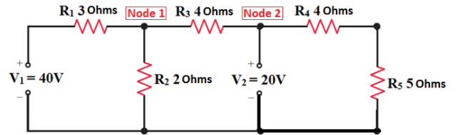
Q: For the circuit given in figure 7 apply Node Voltage Analysis and voltage and current across R1 and…
A: Solution: consider the given diagram, Node 2=V2 V2=20V Because there is no voltage drop between node…
For the circuit given in figure 7 apply Node Voltage Analysis and voltage and current across R1 and R5.

Step by step
Solved in 4 steps with 4 images


- _____ predicts that transistor density will double every two years or less.Q2. Determine Ic, VE, Ve, Veg, VB, R1Computer Science if a 12-bit linear pcm code with a resolution of 0.188V, if the voltage range that would be converted to the pcm code: 111110111101 is in the form X volts to Y volts where X and Y are constants. Find X+Y
- 1. MBR (20:27) and MBR (28:39) 2. IBR (0:7) and IBR (8:19) 3. IBR (20:27) and IBR (28:39) 4. MBR (0:7) and MBR (8:19)Convert the following CFG's to CNF. 1) S -> aX | Yb X -> S Y -> bY | b 2) S-> AS | SB A-> BS | SA B-> SS 3) S-> SaS | SaSbS | SbSaS | A(Logic Gates:* 7404LS (NOT)* 7408LS (AND)* 7432LS (OR)* 7400LS (NAND)* 7402LS (NOR)* 7486LS (EX-OR)* Decoder 74hc138Or you can use 74HCxx versions.) Task 3: Design a Binary Ripple Carry Adder for 5+3 summation in BCDcoding system. Draw the the circuit diagram by using FullAdder Blocks. Simulate the circuit.
- 61. A terminal multiplexer has six 1200 bps' terminals and 'n' 300 bps terminals connected to it. If the outgoing line is 9600 bps, what is the value of n ? a. 4 b. 8 c. 16 d. 28For the circuit shown below, find the nodal voltages Vi, V, and V; 20 Ohms v | 1oomms V2 400hms |v 13— [ ANV s YO §500th (1)2A Nl i SEPFor tthfeoloowing 8085 instruction determine: t-state, size, and machine cycle for each CMP BINX HXRA BSTAX DLDA 2015H