R=22 R= 10e Ro 2a { R = 10 %3D loor = Rz 2e Is - 7 Is - 8. I7- 9. Ilo - l6. Ill- 1 RponAL- 2. ITOTAL - 6. b Vq 3. Ragalo11- 4. R345678901 - 14 V7 5 Raum /11/-
R=22 R= 10e Ro 2a { R = 10 %3D loor = Rz 2e Is - 7 Is - 8. I7- 9. Ilo - l6. Ill- 1 RponAL- 2. ITOTAL - 6. b Vq 3. Ragalo11- 4. R345678901 - 14 V7 5 Raum /11/-

Electricity for Refrigeration, Heating, and Air Conditioning (MindTap Course List)
10th Edition
ISBN:9781337399128
Author:Russell E. Smith
Publisher:Russell E. Smith
Chapter9: Components For Electric Motors
Section: Chapter Questions
Problem 15RQ

Related questions
Question
100%
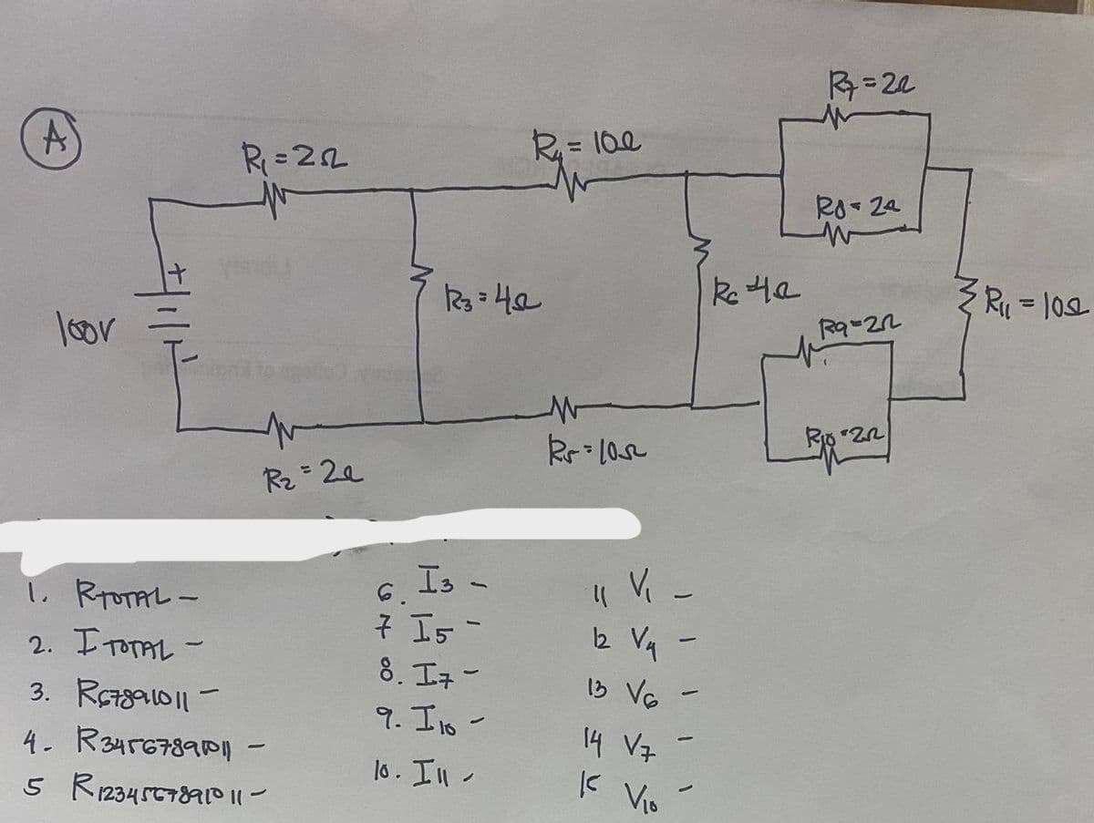
Transcribed Image Text:R=22
R= 10e
Ro 2a
R= 102
loor
Rz= 2e
1. RpoTAL-
2. ITOTAL -
Is -
7 Is -
8. I7-
6.
12 Vq -
1B VG
3. R7gaw|| -
9. Ils -
16
4- R34r67890n
5 R12345C789P Il-
14 V7
lo. Il-
K Vio
/11/-
Expert Solution
This question has been solved!
Explore an expertly crafted, step-by-step solution for a thorough understanding of key concepts.

Step by step
Solved in 2 steps with 4 images

Knowledge Booster


Learn more about
Need a deep-dive on the concept behind this application? Look no further. Learn more about this topic, electrical-engineering and related others by exploring similar questions and additional content below.Recommended textbooks for you
Electricity for Refrigeration, Heating, and Air C…
Mechanical Engineering
ISBN:
9781337399128
Author:
Russell E. Smith
Publisher:
Cengage Learning
Electricity for Refrigeration, Heating, and Air C…
Mechanical Engineering
ISBN:
9781337399128
Author:
Russell E. Smith
Publisher:
Cengage Learning