Resistance

Power System Analysis and Design (MindTap Course List)
6th Edition
ISBN:9781305632134
Author:J. Duncan Glover, Thomas Overbye, Mulukutla S. Sarma
Publisher:J. Duncan Glover, Thomas Overbye, Mulukutla S. Sarma
Chapter3: Power Transformers
Section: Chapter Questions
Problem 3.11P: For the transformer in Problem 3.10. The open-circuit test with 11.5 kV applied results in a power...

Related questions

Question
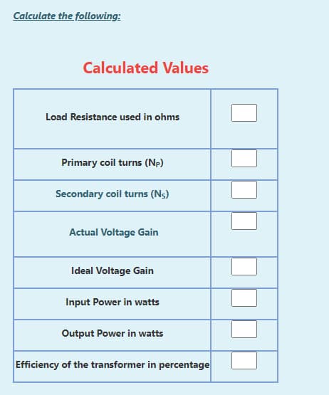
Transcribed Image Text:Calculate the following:
Calculated Values
Load Resistance used in ohms
Primary coil turns (Np)
Secondary coil turns (Ns)
Actual Voltage Gain
Ideal Voltage Gain
Input Power in watts
Output Power in watts
Efficiency of the transformer in percentage
![In the transformer experiment performed in the lab, following coils were used to form a step up transformer:
200
800
100 2
2W
100
2W
And the observed experimental values are tabulated below:
Measured Experimental Values
Input voltage Input Current Output Voltage Output current
Vs [V]
Vp [V]
Ip [A]
Is [A]
5.85
0.904
15.65
0.17](/v2/_next/image?url=https%3A%2F%2Fcontent.bartleby.com%2Fqna-images%2Fquestion%2Ffa173473-29ff-46b3-8eeb-c3d7d926b1de%2F7f1e3803-55f5-4515-a386-2d56beb5976d%2Fxgu5nho_processed.jpeg&w=3840&q=75)
Transcribed Image Text:In the transformer experiment performed in the lab, following coils were used to form a step up transformer:
200
800
100 2
2W
100
2W
And the observed experimental values are tabulated below:
Measured Experimental Values
Input voltage Input Current Output Voltage Output current
Vs [V]
Vp [V]
Ip [A]
Is [A]
5.85
0.904
15.65
0.17
Expert Solution
This question has been solved!
Explore an expertly crafted, step-by-step solution for a thorough understanding of key concepts.

Step by step
Solved in 2 steps with 2 images

Knowledge Booster


Learn more about
Need a deep-dive on the concept behind this application? Look no further. Learn more about this topic, electrical-engineering and related others by exploring similar questions and additional content below.Recommended textbooks for you
Power System Analysis and Design (MindTap Course …
Electrical Engineering
ISBN:
9781305632134
Author:
J. Duncan Glover, Thomas Overbye, Mulukutla S. Sarma
Publisher:
Cengage Learning
Power System Analysis and Design (MindTap Course …
Electrical Engineering
ISBN:
9781305632134
Author:
J. Duncan Glover, Thomas Overbye, Mulukutla S. Sarma
Publisher:
Cengage Learning