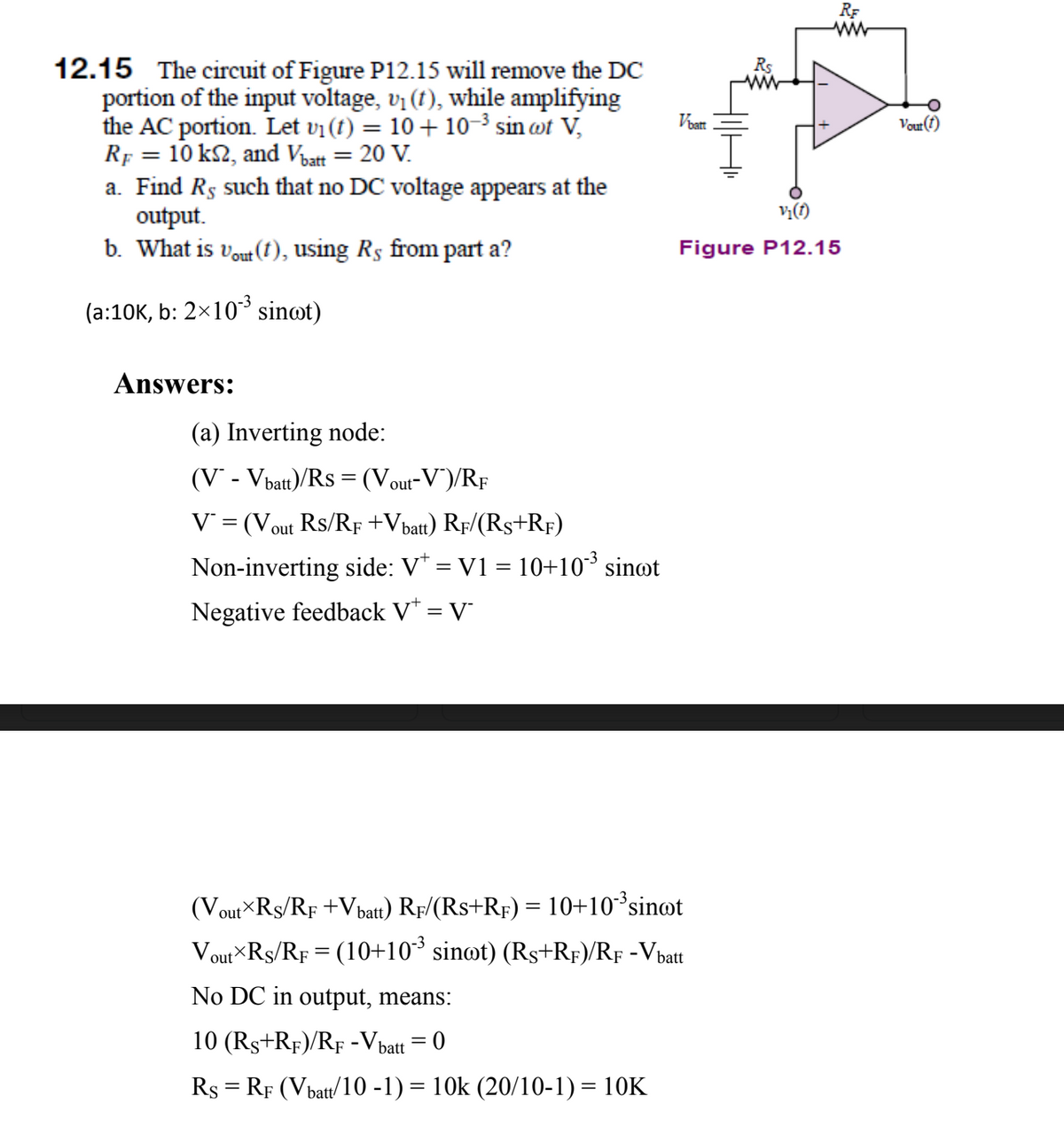
RF ww 12.15 The circuit of Figure P12.15 will remove the DC portion of the input voltage, vi (t), while amplifying the AC portion. Let vi (t) = 10 + 10- sin wt V, Rf = 10 k2, and Vbatt = 20 V. a. Find Rs such that no DC voltage appears at the output. b What is v. (t) using Re from part a? Voat Vour(t) v;(1) Figure P12.15

Introductory Circuit Analysis (13th Edition)
13th Edition
ISBN:9780133923605
Author:Robert L. Boylestad
Publisher:Robert L. Boylestad
Chapter1: Introduction
Section: Chapter Questions
Problem 1P: Visit your local library (at school or home) and describe the extent to which it provides literature...
icon
Related questions
Question

For part(a) of the question, how is 10-3sin(wt) got rid in the equation after "no DC in output..."

Also, why is the KCL eqn at the node : Is+Iin = If    instead of Is+If = Iin ? Does it matter whcih direction of current i choose?

RF
ww
12.15 The circuit of Figure P12.15 will remove the DC
portion of the input voltage, v (t), while amplifying
the AC portion. Let vi (t) = 10 + 10-3 sin ot V,
Rf = 10 k2, and Voatt = 20 V.
a. Find Rs such that no DC voltage appears at the
output.
b. What is vout (1), using Rs from part a?
Rs
Voatt
Vour(1)
vị(1)
Figure P12.15
(a:10K, b: 2×10* sinot)
swers:
(a) Inverting node:
(V* - Vbatt)/Rs = (Vout-V)/RF
V = (Vout Rs/RF +Vbatt) Rf/(Rs+RF)
Non-inverting side: V* = V1 = 10+10³ sinøt
Negative feedback V* = V
(Vout Rs/RF +Vbatt) Rf/(Rs+Rf) = 10+10³sin@t
Vout×Rs/RF = (10+10³ sinot) (Rs+Rf)/RF -Vbatt
No DC in output, means:
10 (Rs+Rf)/RF -Vbatt
Rs = RF (Vbatt/10 -1) = 10k (20/10-1) = 10K
Transcribed Image Text:RF ww 12.15 The circuit of Figure P12.15 will remove the DC portion of the input voltage, v (t), while amplifying the AC portion. Let vi (t) = 10 + 10-3 sin ot V, Rf = 10 k2, and Voatt = 20 V. a. Find Rs such that no DC voltage appears at the output. b. What is vout (1), using Rs from part a? Rs Voatt Vour(1) vị(1) Figure P12.15 (a:10K, b: 2×10* sinot) swers: (a) Inverting node: (V* - Vbatt)/Rs = (Vout-V)/RF V = (Vout Rs/RF +Vbatt) Rf/(Rs+RF) Non-inverting side: V* = V1 = 10+10³ sinøt Negative feedback V* = V (Vout Rs/RF +Vbatt) Rf/(Rs+Rf) = 10+10³sin@t Vout×Rs/RF = (10+10³ sinot) (Rs+Rf)/RF -Vbatt No DC in output, means: 10 (Rs+Rf)/RF -Vbatt Rs = RF (Vbatt/10 -1) = 10k (20/10-1) = 10K
Expert Solution
trending now

Trending now

This is a popular solution!

steps

Step by step

Solved in 4 steps

Blurred answer
Knowledge Booster
KVL and KCL
Learn more about
Need a deep-dive on the concept behind this application? Look no further. Learn more about this topic, electrical-engineering and related others by exploring similar questions and additional content below.
Similar questions
  • SEE MORE QUESTIONS
Recommended textbooks for you
Introductory Circuit Analysis (13th Edition)
Electrical Engineering
ISBN:
9780133923605
Author:
Robert L. Boylestad
Publisher:
PEARSON
Delmar's Standard Textbook Of Electricity
Electrical Engineering
ISBN:
9781337900348
Author:
Stephen L. Herman
Publisher:
Cengage Learning
Programmable Logic Controllers
Electrical Engineering
ISBN:
9780073373843
Author:
Frank D. Petruzella
Publisher:
McGraw-Hill Education
Fundamentals of Electric Circuits
Electrical Engineering
ISBN:
9780078028229
Author:
Charles K Alexander, Matthew Sadiku
Publisher:
McGraw-Hill Education
Electric Circuits. (11th Edition)
Electrical Engineering
ISBN:
9780134746968
Author:
James W. Nilsson, Susan Riedel
Publisher:
PEARSON
Engineering Electromagnetics
Electrical Engineering
ISBN:
9780078028151
Author:
Hayt, William H. (william Hart), Jr, BUCK, John A.
Publisher:
Mcgraw-hill Education,