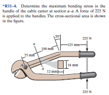
*RII-4. Determine the maximum bending stress in the handle of the cable cutter at section a-a. A force af 225 N is applied to the handles. The cross-sectional area is shown in the figure. 225 N -125 mm- 100 mm 5 mf 18 mm 12 mm 225 N
Q: Q3: The wooden section of the beam is reinforced with two steel plates as shown. If the beam is…
A:
Q: A composite beam is made of two brass [E = 98 GPa] plates bonded to an aluminum [E = 60 GPa] bar, as…
A:
Q: *RII-4. Determine the maximum bending stres in the handle of the cable cutter at section a-a. A…
A: For solution refer below images.
Q: Q4: If the cross section of the beam shown in the figure (3) below has bending stress of 28 MN/m² in…
A:
Q: Q1) A beam has a loadingsystem as shownin the figure below. (1) draw the shear diagam (2) m om ent…
A: Solution: Note: Dear Student! As per our guidelines, we are only allowed to answer a single…
Q: The screw of the clamp exerts a compressive force of 500 N on the wooden blocks. The cross section…
A: Given: The compressive force on wooden block, P = 500 N The cross-section of clamp at a-a, A = 3 cm…
Q: A solid steel shaft, circular in cross section, has a change in diameter from 135 mm to 90 mm with a…
A:
Q: The steel beam has the cross- Wo section shown in the figure. Determine the largest possible…
A:
Q: For the beam seen in the loading state in the way find the largest shear stress in the n-n section…
A: Write the expression of length l. Write the expression of the moment of inertia of the beam.
Q: The bending moment acting on the triangular cross section of a beam is 3.6 kN m. Determine the…
A:
Q: Q1) A simply supported beam having a length of 7 meters carries a uniformly distributed load of…
A: Any action that can change the state of motion is called force, Force is described by its magnitude,…
Q: A composite beam is made of two brass [E = 118 GPa) plates bonded to an aluminum [E = 60 GPa) bar,…
A:
Q: A beam of a T cross section is formed by nailing together two boardshaving the dimensions shown in…
A: Given Data The maximum force acting on the cross section is: F=1500 N The load carried by each nail…
Q: An aluminum [E = 10000 ksi] bar is bonded to a steel [E = 30000 ksi] bar to form a con = 2.00 in.…
A:
Q: A steel pipe (D = 3.500 in.; d = 3.068 in.) supports a concentrated load of P = 500 lb as shown. The…
A:
Q: The bent link has a circular cross section with a diameter of d=15 mm and it is subjected to the…
A:
Q: The beam ABCD with a rectangular cross section carries the loading shown in the figure. Determine…
A:
Q: 6-54. The beam is made from three boards nailed together as shown. If the moment acting on the cross…
A: Given: Moment acting on the cross section - M = 600Nm To Find: Maximum bending stress in beam.
Q: Determine the maximum bending stress in the beam with the circular cross-section. 400 lb B 200 lb/ft…
A: First of all, find the reaction at the supports Ay+Cy=400+(200)9 Ay+Cy=2200 ...(1)
Q: 2. If the bending stress at section 2 =20 MPa. What are the bending stresses at sections 1, 3, and…
A: Given data: From equation of pure bending MI=σby=ER…
Q: R₁ -2m- B -2m- 30 kN/m -5m- C D R₂
A: Draw the shear force and bending moment diagram and find its maximum values in the beam.
Q: A composite beam is made of two brass [E = 112 GPa] plates bonded to an aluminum [E = 64 GPa] bar,…
A:
Q: Q4: If the T- cross section of the beam shown in the Figure (3) below has bending stress of 37 MN/m2…
A:
Q: *RII-4. Determine the maximum bending stress in the handle of the cable cutter at section a-a. A…
A: Given: The load acting on the handle, P = 22 kN The load parallel to the section a-a, The moment…
Q: 1 Draw shear and moment diagram. Det. max. V and max. M 2. Draw loading and moment diagram given the…
A:
Q: The solid shaft is fixed to the support at C and subjected to the torsional loadings T = 15 kN.m and…
A:
Q: If a circular shaft is subjected to a torque T and a bending moment M, the ratio of the maximum…
A:
Q: A concentrated load of P = 20 kN is applied to the upper end of a pipe with length L = 5 m. The…
A:
Q: Ex. No. 3: Determine the values of the shear stress owing to bending at point A, B3, and C in the…
A:
Q: in the figure. (a) Determine the shear force V and bending moment M at a cross section located 18 ft…
A:
Q: Question 5 Determine the normal force, shear force, and moment at point D of the structure in Figure…
A:
Q: A solid shaft with a diameter of 20 mm is shown below. The shaft is fixed at points A and B. In the…
A: As per given question question a) Draw a torque diagram for this shaft. b) Determine the maximum…
Q: 6-126 The wooden section of the beam is reinforced with two stedl plate as shown. II the beam is…
A:
Q: 2. A shaft made of mild steel. The supported length of the shaft is 3 meters. It carries two pulleys…
A: From the figure it is clear that the beam is subjected to symmetric loading Therefore, RA=RB…
Q: Q.2 The red steel pipe below has a concentrated load P = 880 lb applied at its end. The total length…
A: Given data Load p = 880 lb Pipe dimensions Length = 4ft Outer diameter= 4.2 in Inner…
Q: Q. 3: Compare the moment of resistance of the two sections for equal areas of cross-section and of…
A:
Q: 6-54. The beam is made from three boards nailed together as shown. If the moment acting on the cross…
A: The centroid is the center of the unshaped body which made from a shaped body. It is the point at…
Q: 2 lgium M=1.96 KN-mm Detrmine a bending stresses of beam. 200mm 125 3 50 250 mm. 125mm 25 -1
A:
Q: Q13: In the figure, the (a , ) bending stress equal ---- if the moment inertia 5 m and the…
A:
Q: The beam is subjected to a moment M=17.6 kN-m. Determine the maximum bending stress given a=60 mm…
A:
Q: The beam shown below has a cross section of channel shape with width b-200 mm and height h=80 mm,…
A: Given Data: Length of the beam, L=4.5 m
Q: A cast iron pulley transmits 20 kW at 300 r.p.m. The diameter of the pulley is 550 mm and has four…
A: Given data in this problem is ⇒Power that pulley can transmits(P) =20 kW⇒Speed(N) = 300 rpm⇒Diameter…
Q: A wood beam is reinforced with steel straps at its top and bottom as shown. Determine the maximum…
A: Moment of inertia of beam can be determined as
Q: for the loaded beam as shown in the figure on the m-m section a) the greatest value of shear stress…
A:
Q: The bending moment acting on the triangular cross section of a beam is M = 36 kN.m (concave upward).…
A: Data given -
Q: Hwi Abeam had subjected to a postive bending moment of 5 KN.m. The ưoss-Sedionae dimensions are…
A:
Q: Find the bending stress at point B located at mid-span of the rod 5 N/m O.Scm Ø 2 cm 0.5m. Tm 16 N
A: Consider horizontal forward & vertically upward force as (+)ve and vertically downward force as…
Q: A solid steel shaft, circular in cross section, has a change in diameter from 135 mm to 90 mm with a…
A:
Q: Q/ Find the bending stress at point k ? 10 mm 5 kN-m 40 mm 5 kN-m K 150 mm H 15 120 mm
A:
Q: Q1) A simply supported beam is 3 m long and carries a vertical load of 5 kN at point Im from the…
A: Given: Vertical load =5kNClockwise moment=3kN.m
determine the maximum bending stress at the section aa of the cable cutter handle applies 225 N force to the handles cross sectional area shown in the figure
Step by step
Solved in 2 steps with 2 images
- The T-beam shown in the figure has cross-sectional dimensions: b = 210 mm, t = 16 mm, h = 300 mm, and A, = 280 mm. The beam is subjected to a shear force V = 68 kN. Determine the maximum shear stress tntijlin the web of the beam.A cant i levé r b ea m i s supported by a tie rod at B as shown. Both the tie rod and the beam are steel with E = 30 x 106 psi. The tie rod is just taut before the distributed load q = 200 lb/ft is applied. Find the tension force in the tie rod. Draw shear-force and bending-moment diagrams for the beam, labeling all critical ordinates.A hollow steel box beam has the rectangular cross section shown in the figure. Determine the maximum allowable shear force K that may act on the beam if the allowable shear stress is 36 MPa. c
- A thin-walled rectangular tube has uniform thickness t and dimensions a x b to the median line of the cross section (see figure). How does the shear stress in the tube vary with the ratio = a/b if the total length Lmof the median line of the cross section and the torque T remain constant? From your results, show that the shear stress is smallest when the tube is square (ß = 1).A beam having a cross section in the form of an un symmetric wide-flange shape (sec figure) is subjected to a negative bending moment acting about the 2 axis. Determine the width b of the top flange in order that the stresses at the top and bottom of the beam will be in the ratio 4:3, respectively.A circular pole is subjected to linearly varying distributed force with maximum intensity t0. Calculate the diameter daof the pole if the maximum allowable shear stress for the pole is 75 M Pa.
- A small dam of a height h = 6 ft is constructed of vertical wood beams AB, as shown in the figure. The wood beams, which have a thickness I = 2.5 in., are simply supported by horizontal steel beams at A and Ä Construct a graph showing the maximum bending stress tram in the wood beams versus the depth d of the water above the lower support at B. Plot the stress0mas(psi) as the ordinate and the depth d(ft) as the abscissa. Note: The weight density y of water equals 62.4 lb/ft3.Derive the following formula for the distance e from the centerline of the wall to the shear center S for the hat section of constant thickness shown in the figure: Also, check the formula for the special case of a channel section (a = 0).The horizontal beam ABC of an oil-well pump has the cross section shown in the figure. If the vertical pumping force acting at end C is 9 kips and if the distance from the line of action ofthat force to point B is 16 ft, what is the maximum bending stress in the beam due to the pumping force?
- Two W 310 × 74 Steel wide-flange beams are bolted together to form a built-up beam as shown in the figure. What is the maximum permissible bolt spacing s if the shear force V = 80 kN and the allowable load in shear on each bolt is F = 13.5 kN. Note: Obtain the dimensions and properties of the W shapes from Table F-l(b).An A-36 steel strap having a thickness of 10 mm and a width of 20 mm is bent into a circular arc of radius r = 10 m. Determine the maximum bending stress in the strap.A shaft is made of a polymer having an elliptical cross section. If it resists an internal moment of M = 50 N # m, determine the maximum bending stress in the material (a) using the flexure formula, where Iz = 1 4 p(0.08 m)(0.04 m)3, (b) using integration. Sketch a three-dimensional view of the stress distribution acting over the cross-sectional area. Here Ix = 1 4 p(0.08 m)(0.04 m)3.