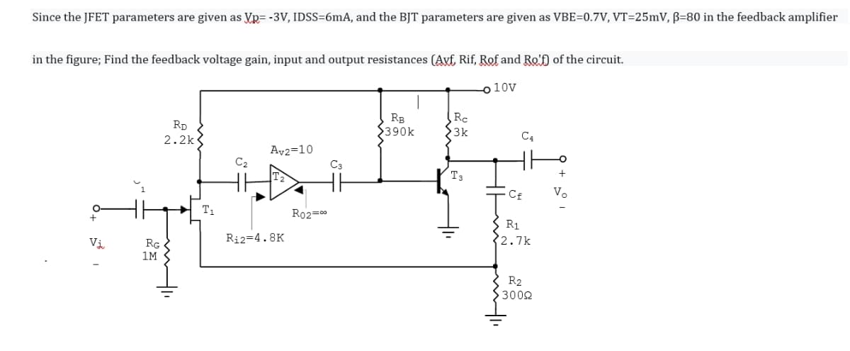
Since the JFET parameters are given as Vp= -3V, IDSS=6mA, and the BJT parameters are given as VBE=0.7V, VT=25mV, B=80 in the feedback amplifier in the figure; Find the feedback voltage gain, input and output resistances (Ayf, Rif, Rof and Ro'f) of the circuit.


Q: Parameter Minimum | Typical Maximum Units de supply voltages Vs Input offset voltage Vos Thermal…
A:
Q: Consider the series-shunt feedback amplifier of Figure below. Assume that the voltage divider (R1,…
A: Given : Series Shunt Feedback Amplifier Voltage divider R1,R2 is implemented with 1M ohm…
Q: 40. Given that fc(ol) = 100 Hz, Aol = 50 dB, and fc(cl) = 3 kHz, determine the closed-loop gain in…
A: The required parameters can be calculated by using the unity gain bandwidth and the closed loop…
Q: Find the desired values below in the feedback amplifier circuit in Figure 2. a. Find the no-load…
A:
Q: 1. Consider the unity feedback system below R(s) + E(s) C(s) G(s) K G(s) (s + 4)³ 2. Find the…
A: Solve first three sub-parts in a multiple sub-part question, unless the student has asked for…
Q: Find the loop gain, ideal current gain, actual current gain, input resistance, and output resistance…
A: Calculating ideal current gain
Q: For the amplifier shown below, Find the closed-loop gain and the output impedance. Parameters:…
A: Given the circuit, as shown below: Given the value of parameters: R1 = 805Ω, R2 = 3kΩ, ro1 = ro2 =…
Q: b) What are the effect of negative feedback on gain and bandwidth? Confirm your answer by drawing…
A: The answer as given below:
Q: Feedback: 2. An ideal series-shunt feedback amplifier has Rs negligibly small. If Vi = 100mV, Vfb…
A: Series-shunt feedback system: This system works as the true voltage amplifier because the input…
Q: Q) In the negative feedback the low frequency and the high frequency with the feedback are: Note:…
A:
Q: (2) suppose the open-loop amplifier (or simply the OpAmp) in the above feedback amplifier has the…
A: The magnitude response is the ratio of the output signal's frequency amplitude to the input signal's…
Q: 4. (a) Determine the marginal value of K using gain margin and phase margin for the unity feedback…
A:
Q: The transistor parameters for the circuit shown are VTN = 0.4 V, Kn = 0.5 mA/V2, and λ = 0. (a)…
A:
Q: for identical transistors Hfe=100 and hie=2,5K. according to the elements and values given on the…
A: It is given the identical transistors hfe=100 , hie=2.5 kΩ We need to determine the feedback…
Q: Feedback: 3. An ideal shunt-shunt feedback amplifier has Rs =∞ . If Ii = 100 microAmp, I fb = 99…
A:
Q: The circuit as shown is a shunt-shunt feedback amplifier. Use feedback analysis to find the midband…
A: The equivalent circuit diagram for the given shunt-shunt feedback amplifier is shown in the…
Q: For the amplifier circuit shown, determine the current gain Ai = lo/Ils using ideal feedback…
A: Given data is- hfe1=hfe2=100hie1=30 kΩhie2=1.5 kΩRL=1 kΩRC=0.1 kΩ Calculating Current gain A=I∘Is
Q: Q) An amplifier has voltage gain with the feedback of 100. If the gain without feedback changes by…
A:
Q: Q) In the negative feedback the low frequency and the high frequency with the feedback are: Note:…
A:
Q: Show that negative feedback can reduce the sensitivity of an amplifier circuit, by deducing the…
A: According to guidelines, we are allowed to solve only first 3 subparts. Since the second subpart…
Q: The AC equivalent of a feedback amplifier circuit is given in the figure on the right. (Hfe100, Va =…
A: Note-Since we only answer up to 3 sub-parts, we’ll answer the first 3. Please resubmit the question…
Q: Consider the series-shunt feedback amplifier of Figure below. Assume that the voltag divider (R1,…
A: The given circuit diagram is shown below: It is given that: gm=4 mA/VRD=10 KΩClosed loop…
Q: 1- What is the useful bandwidth of the amplifier? 2- How to prove that, positive feedback increase…
A: We need to explain what is the useful bandwidth of amplifier and how to prove that positive feedback…
Q: Find the loop gain, ideal transconductance, actual transconductance, input resistance, and output…
A: To calculate the loop gain, ideal transconductance, actual transconductance, input resistance, and…
Q: Which of the following is true about the ( + 2)* Root-ground curve of a negative unit feedback…
A: Given open loop transfer function is - Given that system is negative unity feedback system.
Q: Choose an answer for each question. (You will choose three answers in total.) Her bir soru için bir…
A: Right Answer option (I) (J) (K)
Q: A unity feedback system has the open loop transfer function shown below. Use the Nyquist Path that…
A: In this question we need to find a value of N for large k
Q: (2) suppose the open-loop amplifier (or simply the OpAmp) in the above feedback amplifier has the…
A: The magnitude response is the ratio of the frequency amplitude of the output signal to the frequency…
Q: Q3: Prove that: 1:- Ac-Current gain of collector feedback amplifier is a proximally Rp/Rc.…
A: For the given question We have to prove : Ac-current gain of collector feedback amplifier :…
Q: 3- Consider the ideal Current Shunt feedback amplifier. Assume that the source resistance is Rs =0.…
A:
Q: 6) For a unity feedback system whose open :, loop transfer function is given by K G(s)H(8) = s(s2 +…
A:
Q: Q) An amplifier has voltage gain with the feedback of 100. If the gain without feedback changes by…
A:
Q: Consider the series-shunt feedback amplifier of Figure below. Assume that the voltage divider (R1,…
A: Given the series-shunt feedback amplifier in the figure. And also given the value RD =10 ohm, close…
Q: Q1:For the collector feedback amplifier it's parameter B=120and Vcc=16 V, R-3k2, Rg=1kQ, Rp=260kQ…
A: *Keeping a note ?as per our company guidelines we are supposed to answer ?️only first 3️⃣ sub-parts.…
Q: The feedback capacitance of an inverting amplifier is 13 pF. What is the Miller capacitance at the…
A: We will use Miller theorm to find input capacitance.
Q: An amplifier has an open-loop voltage gain of 90 dB, Rid = 50 kΩ, and Ro = 5000 Ω. The amplifier is…
A: Part (a): The open-loop voltage gain is given by: AvdB=90 dB20logAv=90 dBAv=31622.78
Q: A unity feedback system has a forward path transfer function K Gs) = s(s+ 8) %3D where K is the gain…
A: Given Gs=Kss+8Hs =1 Closed loop transfer function =Gs1+GsHs…
Q: gain of 10 is required from a noninverting constant-multiplier op-amp circuit. If the input resistor…
A: We need to find out the value of feedback resistance for given amplifier
Q: Consider an amplifier with the loop gain function T(f), where ßis the feedback gain and frp is the…
A: Given: Consider an amplifier with the loop gain function T(f): Tf=β1041+jffPD1+jf105 where β is the…
Q: QI:For the collector feedback amplifier it's parameter B-120and Vcc Rg=260kQ determine: 1-S(Ico)…
A: *Keeping a note ?as per our company guidelines we are supposed to answer ?️only first 3️⃣ sub-parts.…
Q: Q1): Sketch the polar plot for the unity feedback system shown below and compute the gain margin and…
A: We will first plot the Nyquist plot of the given transfer function. As we know the polar plot is a…
Q: Parameter Minimum Typical Maximum Units de supply voltages Vs Input offset voltage Vos Thermal drift…
A:
Q: Q10: Obtain the transfer function C(s)/R(s) for the system shown in figure (10). Use 1- Block…
A: Given block diagram
Q: Given in the figure is a two-stage amplifier design that employs negative feedback. Answer the…
A: Given the circuit, as shown below: Given in the figure is a two-stage amplifier design that employs…
Q: Q) In the negative feedback the low frequency and the high frequency with the feedback are (a) flf=…
A: In nagative feedback feed back signal is out of phase with the input signal. So gain will decrease…
Q: Figure 6 shows a circuit where feedback is provided between the drain and gate of the transistor M1…
A:
Q: Which among the choices is true about closed loop amplifier? Adds stability to the amplifier.…
A: The question is related to the closed loop amplifier

Step by step
Solved in 7 steps with 5 images

- The circuit as shown is a shunt-shunt feedback amplifier. Use feedback analysis to find the midband input resistance, output resistance, and transresistance of the amplifier if RI = 500 Ω, RE = 2 kΩ, β0 = 100, VA = 50 V, RL = 5.6 kΩ, and RF = 47 kΩ, when vi and RI are replaced by a Norton equivalent circuit. What is the voltage gain for the circuit as drawn?The transistor parameters for the circuit shown are VTN = 0.4 V, Kn =0.5 mA/V2, and λ = 0.(a) Discuss the feedback topology, show the input ant output connections (series orshunt)(b) Find the feedback factor β (find the transfer function without feedback first)Find the loop gain, ideal transconductance, actual transconductance, input resistance, and output resistance for the feedback amplifier as shown with RI =15 kΩ, RL =10 kΩ, and R1 =3kΩ.
- Find the loop gain, ideal transresistance, actual transresistance, input resistance, and output resistance for the feedback amplifier shown with RI =100kΩ, RL =15kΩ, and RF =10kΩ.Find the loop gain, ideal current gain, actual current gain, input resistance, and output resistance for the feedback amplifier shown with RI = 150 kΩ, RL = 5k Ω, R1 = 10 kΩ and R 2 =1kΩ.Find the desired values below in the feedback amplifier circuit in the figure. a) Find the no-load voltage gain in the amplifier circuit when the Rf resistor is open circuit. b) Voltage and current in amplifier circuit when Rf resistor is open circuit and RL resistor is present Find your earnings. c) When the Rf feedback resistor is connected, the Rf value that makes the feedback current gain Ai/3 find it. Indicate the assumptions you take in your transactions.
- 40. Given that fc(ol) = 100 Hz, Aol = 50 dB, and fc(cl) = 3 kHz, determine the closed-loop gain in decibels What is the unity-gain bandwidth in Problem 40? 42 to 44. For each amplifier in the Figures shown determine the closed-loop gain, Acl and bandwidth, BWcl. The op-amps in each circuit exhibit an open-loop gain, Aol of 100 dB and a unity-gain bandwidth, fT of 1 MHzFind the desired values below in the feedback amplifier circuit in Figure 2.a. Find the no-load voltage gain in the amplifier circuit while the Rf resistance is open circuit. b. Find the voltage and current gain in the amplifier circuit, while the Rf resistance has an open circuit and the RL resistance.c. Find the Rf value that makes the feedback current gain Ai/3 when the Rf feedback resistor is connected. Indicate the assumptions you receive in your transactions. β = 75Slove Boperational amplifiers of your choice both FET and BJT based technology (make sure datasheets areavailable with your final report):A) From the datasheet, find the number of pins of the Op-amp IC, the open-loop gain,bandwidth, CMRR, slew rate, Voltage offset, current offset, input and output impedance,recommended supply voltages. Tabulate your outcomes with evidence from the data sheets.For both types of Op-Amps. Discus advantages and disadvantages of both.B) Mention available amplifiers that this op-amp is used for and discuss in brief itsapplications.
- 2-) The AC equivalent of a feedback amplifier circuit is given in the figure on the right. (Hfe100, Va = ∞, Ic1 = 15 mA, Ic2 = 5mA and Ic3 = 5 mA) a) State the type of feedback used in the circuit, explaining the reason. b) Draw the small signal equivalent of the amplifier circuit. c) Calculate the value of β for the feedback by drawing the β circuit. d) Find the Avf = Vo / Vs closed loop gain of this circuit. e) Find the Rif and Rof values.Find the desired values below in the feedback amplifier circuit in Figure 2.a. Find the no-load voltage gain in the amplifier circuit while the Rf resistance is open circuit. b. Find the voltage and current gain in the amplifier circuit, while the Rf resistance has an open circuit and the RL resistance.c. Find the Rf value that makes the feedback current gain Ai/3 when the Rf feedback resistor is connected. Indicate the assumptions you receive in your transactions.Given in the figure is a two-stage amplifier design that employs negative feedback. Answer the following questions. Use the notation (R1 + R2 + ... + Rn) for series resistors and (R1 || R2 || ... || Rn) for parallel resistors for clarity and ease. Assume that the transistors are already biased properly in the saturation region and ro1 = ro2 → ∞. Also assume that the capacitors have infinite capacitance. 1.) Find the expression for the open loop gain Av 2.) Derive the resistance Rin which is the resistance that can be seen at the input port of the amplifier