Single phase, full wave uncontrolled rectifier using resistive load, R=15 ohm, Vs=100V, find 1- average voltage and current 2- RMS voltage and current 3-Power factor 4 sketch the out voltage, current, and diode voltage
Single phase, full wave uncontrolled rectifier using resistive load, R=15 ohm, Vs=100V, find 1- average voltage and current 2- RMS voltage and current 3-Power factor 4 sketch the out voltage, current, and diode voltage

Chapter59: Motor Startup And Troubleshooting Basics
Section: Chapter Questions
Problem 12SQ: How is a solid-state diode tested? Explain.

Related questions
Question
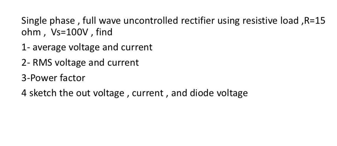
Transcribed Image Text:Single phase, full wave uncontrolled rectifier using resistive load, R=15
ohm, Vs=100V, find
1- average voltage and current
2- RMS voltage and current
3-Power factor
4 sketch the out voltage, current, and diode voltage
Expert Solution
This question has been solved!
Explore an expertly crafted, step-by-step solution for a thorough understanding of key concepts.

Step by step
Solved in 3 steps with 2 images

Knowledge Booster


Learn more about
Need a deep-dive on the concept behind this application? Look no further. Learn more about this topic, electrical-engineering and related others by exploring similar questions and additional content below.Recommended textbooks for you

Electricity for Refrigeration, Heating, and Air C…
Mechanical Engineering
ISBN:
9781337399128
Author:
Russell E. Smith
Publisher:
Cengage Learning
Electricity for Refrigeration, Heating, and Air C…
Mechanical Engineering
ISBN:
9781337399128
Author:
Russell E. Smith
Publisher:
Cengage Learning