state machin resented by the table in Table A2-3 to be implemented in equential logic. There is one input named, "mode", and 1 output named, "select". Table A2-1 Next State: mode = 0 Next State: mode = 1 Current State Next State, select Next State, select A A,0 3,0 B B,0 C,0
state machin resented by the table in Table A2-3 to be implemented in equential logic. There is one input named, "mode", and 1 output named, "select". Table A2-1 Next State: mode = 0 Next State: mode = 1 Current State Next State, select Next State, select A A,0 3,0 B B,0 C,0

Delmar's Standard Textbook Of Electricity
7th Edition
ISBN:9781337900348
Author:Stephen L. Herman
Publisher:Stephen L. Herman
Chapter13: Magnetic Induction
Section: Chapter Questions
Problem 1PA

Related questions

Question
can you do the last 3 parts
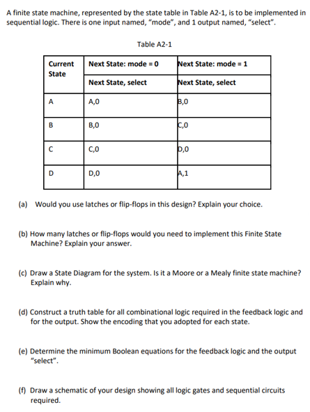
Transcribed Image Text:A finite state machine, represented by the state table in Table A2-1, is to be implemented in
sequential logic. There is one input named, "mode", and 1 output named,"select".
Table A2-1
Current
Next State: mode = 0
Next State: mode = 1
State
Next State, select
Next State, select
A
A,0
3,0
B
B,0
C,0
с
C,0
P,0
D
D,0
A,1
(a) Would you use latches or flip-flops in this design? Explain your choice.
(b) How many latches or flip-flops would you need to implement this Finite State
Machine? Explain your answer.
(c) Draw a State Diagram for the system. Is it a Moore or a Mealy finite state machine?
Explain why.
(d) Construct a truth table for all combinational logic required in the feedback logic and
for the output. Show the encoding that you adopted for each state.
(e) Determine the minimum Boolean equations for the feedback logic and the output
"select".
(f) Draw a schematic of your design showing all logic gates and sequential circuits
required.
Expert Solution
This question has been solved!
Explore an expertly crafted, step-by-step solution for a thorough understanding of key concepts.

Step by step
Solved in 4 steps with 1 images

Follow-up Questions
Read through expert solutions to related follow-up questions below.
Follow-up Question
part d e f

Transcribed Image Text:A finite state machine, represented by the state table in Table A2-1, is to be implemented in
sequential logic. There is one input named, "mode", and 1 output named,"select".
Table A2-1
Current
Next State: mode = 0
Next State: mode = 1
State
Next State, select
Next State, select
A
A,0
3,0
B
B,0
C,0
с
C,0
P,0
D
D,0
A,1
(a) Would you use latches or flip-flops in this design? Explain your choice.
(b) How many latches or flip-flops would you need to implement this Finite State
Machine? Explain your answer.
(c) Draw a State Diagram for the system. Is it a Moore or a Mealy finite state machine?
Explain why.
(d) Construct a truth table for all combinational logic required in the feedback logic and
for the output. Show the encoding that you adopted for each state.
(e) Determine the minimum Boolean equations for the feedback logic and the output
"select".
(f) Draw a schematic of your design showing all logic gates and sequential circuits
required.
Solution
Knowledge Booster


Learn more about
Need a deep-dive on the concept behind this application? Look no further. Learn more about this topic, electrical-engineering and related others by exploring similar questions and additional content below.Recommended textbooks for you
Delmar's Standard Textbook Of Electricity
Electrical Engineering
ISBN:
9781337900348
Author:
Stephen L. Herman
Publisher:
Cengage Learning
Delmar's Standard Textbook Of Electricity
Electrical Engineering
ISBN:
9781337900348
Author:
Stephen L. Herman
Publisher:
Cengage Learning